5.7.1. Fixposition CAN wheelspeed sensor
The CAN message must be formatted as described in Appendix B for a generic speed
input. The user should send the corresponding CAN frames at regular intervals, where
the input rate must be at most 50 Hz. The message latency, measured from computing the
wheelspeed to broadcasting it over the CAN bus, must be as low as possible. Increased
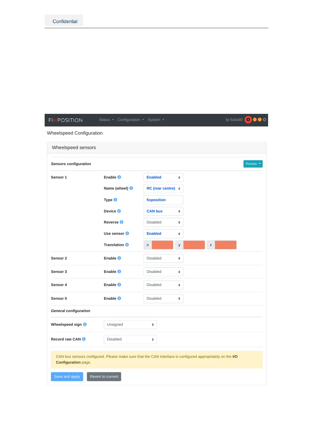
and, in particular, irregular latency degrades the Vision-RTK 2’s performance. The low-
level sensor parameters are automatically filled in when one of the preset settings is
selected. For example, Figure 5.19 presents the configuration when the "Fixposition CAN
message (vehicle speed, CAN)" preset is selected.
Wheelspeed sensors
Presets
Sensor 1 Enable
Name (wheel)
Type
Device
Reverse
Use sensor
Translation
Sensor 2 Enable
Sensor 3 Enable
Sensor 4 Enable
Sensor 5 Enable
General configuration
Wheelspeed sign
Record raw CAN
Sensors configuration
CAN bus sensors configured. Please make sure that the CAN interface is configured appropriately on the I/O
Configuration page.
Status Configuration System fp-5cba80
Figure 5.19.: Fixposition CAN message (vehicle speed) preset configuration
Vision-RTK 2 | Fixposition Positioning Sensor 33