5.2.4. Camera streaming
It is possible to stream the camera image from the following URL:
• http://x.x.x.x/api/v2/camera/stream (ca. 2 MiB/s).
Some notes and warnings:
• Each running stream costs CPU resources and may affect the sensor’s perfor-
mance; use with consideration.
• The stream format is compatible with commercial software like Mozilla Firefox,
Google Chrome, ffmpeg, and VLC. The transport is HTTP, and the stream format is
MJEPG.
• The frame rate is limited (approx. 4 fps).
• The camera stream is only for debugging and development (e.g., checking camera
alignment). Operational and continuous use is not supported.
5.2.5. USB recovery network
When connected to a PC, the USB port on the Vision-RTK2 acts as a "USB Ethernet
gadget." The PC sees a network interface similar to a USB-to-ethernet dongle.
The PC should automatically detect the network interface and configure it. This way,
the user can access the web interface via http://10.0.3.1 to change the configuration. The
configured password does not protect this access mode to the web interface as with other
interfaces (Ethernet and Wi-Fi).
The user cannot configure this network access mode as it is only for recovery (e.g., mis-
configured Ethernet and Wi-Fi) and should not use it for data transfer.
The USB network interface should automatically work on Linux (e.g., Ubuntu 22.04). Win-
dows should recognize the sensor as a "USB Ethernet/RNDIS Gadget," not as a (non-
functional) COM port.
5.2.6. Time synchronization
There are two options:
1. Use NTP protocol over the network. The Vision-RTK 2 has a built-in NTP server
(port 123). You can use that to synchronize your system clock to the very accurate
system clock of the Vision-RTK 2.
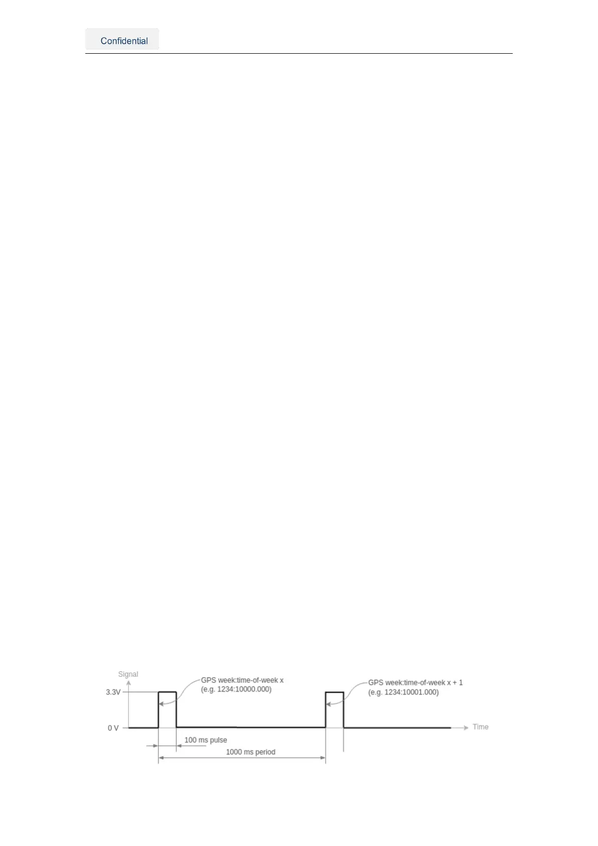
2. The Vision-RTK 2 outputs the PPS signal from the GNSS1 receiver.
• Time pulse over the pin 5 of the I/O connector.
• Time mark over the pin 6 of the I/O connector.
Figure 5.5.: An illustration of time pulse function
Vision-RTK 2 | Fixposition Positioning Sensor 17