FLAMIC S.R.L. 5 Via dell’Artigianato, 36035 Marano Vicentino (Vicenza) - Italy
47
Dough sheeter SF450 - SF500 - SF600 Operation and maintenance manual (translation of original instructions) – Ed. 10/2016
Rev.02 10/2017
All rights reserved. Reproduction in whole or in part of this manual is prohibited.
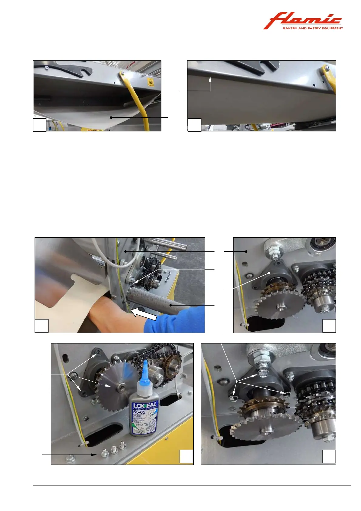
26. with reference to Figure 39, bring the conveyor belt ref. 29 from the condition shown in photo A to the
condition shown in photo B, in which both sides are above the edges ref. 40 of the table.
Figure 39 - SF450 and SF500: preparing the belt before installing the drive roller
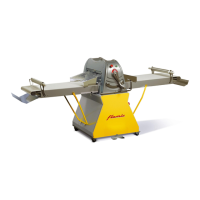
27. with reference to Figure 40, make the necessary space with one hand and with the other insert the roller ref.
22 into the hole ref. 41 of the upright on the controls side ref. 38, passing it inside the belt ref. 29 (photo A)
until the support ref. 19 is in contact with the upright ref. 38 (photo B). After having put some thread locking
compound on the threads (use LOXEAL 55-03 or equivalent), place the screws ref. 18 into the holes ref. 43
and screw them into the corresponding threaded holes in the upright ref. 38 until the support is fixed into
place ref. 19 (photos C - D).
28. using a brush, grease the pin ref. 21 with mechanical assembly grease (wear oil resistant gloves, read the
product safety data sheet and follow the instructions). Then insert the support ref. 17 as far as it will go
onto the pin ref. 21 and at the same time place it in the seat ref. 44 on the upright (photos E - F).
29. place a ø 30 flat ended steel rod ref. 45 against the inner ring of the bearing and hit it using a strong plastic
hammer until the support ref. 17 is flush with the upright ref. 32 (photo G).
30. after having smeared them with the thread locking compound described above, insert the screws ref. 16 into
the holes ref. 46 and tighten them gradually and alternately into the corresponding holes ref. 32 on the
upright until the support ref. 17 is locked securely against the upright ref. 32 (photos H - I).
Start Figure 40 - SF450 and SF500: installing a conveyor belt drive roller
29
40
22
41
38
19
42
43
18
A B
A B
C D