Designs
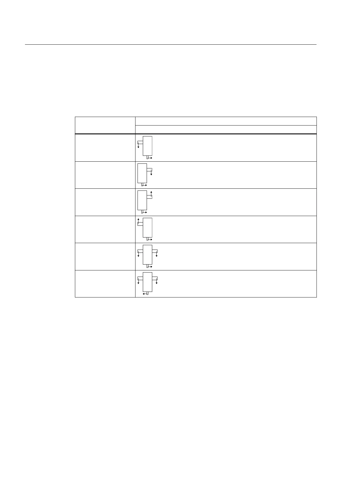
Various shaft arrangements (versions and directions of rotation) are possible. These are
depicted schematically as a solid shaft below. The direction of rotation arrows indicate the
dependency of the direction of rotation of the input and output shafts.
Table 3-1 Designs and associated directions of rotation
Design Type
B3SA, B3HA, B3KA, B3DA, B3SF
A
B
C
D
E
F
The design can be changed from A to C or from B to D by replacing the oil dipstick and the
ventilation and bleeding equipment.
When an auxiliary drive is mounted (as maintenance or load drive), the assignment of the
direction of rotation to the specic version is dened in the dimension drawing.
3.2 Output shaft versions
The following versions of output shaft are available:
• S = solid shaft
• H = hollow shaft with parallel keyway
• D = hollow shaft for shrink disk
• K = hollow shaft with spline according to DIN 5480
The available versions of output shaft are illustrated in the diagram below:
Description
3.2 Output shaft versions
Assembly and operating instructions A5051en
24 Edition 06/2020



 To Next Page