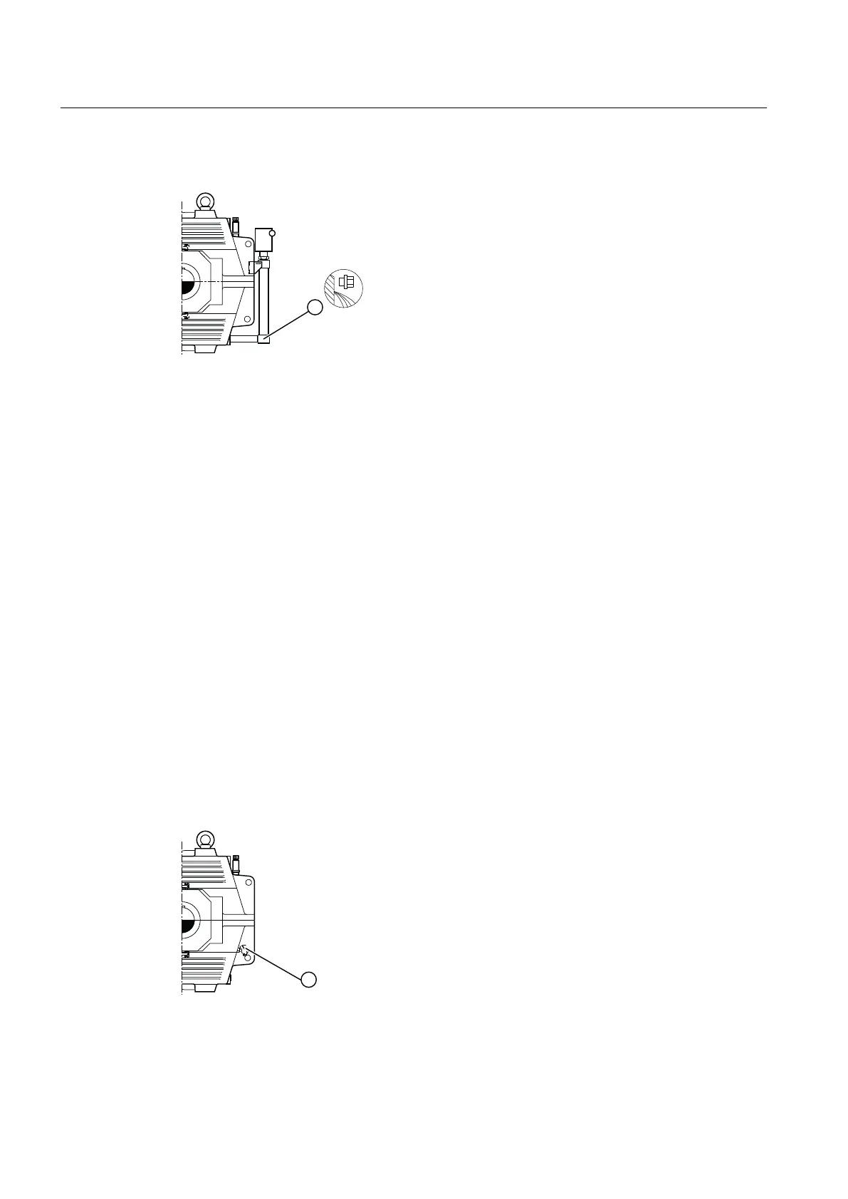
The diagram below shows the oil level monitoring system for the gear unit:
① Oil level monitoring system
Figure 3-12 Ölniveauüberwachung an Getrieben der Bauart B3..
Further information
Further information, a detailed illustration of the gear unit and the position of the mounted
components can be found in the dimension drawing in the complete documentation for the
gear unit.
Further information about oil level monitoring, control instructions and the technical data can
be found in the operating instructions for the oil level monitor, in the list of equipment and in the
separate data sheet in the complete documentation for the gear unit.
3.16 Oil temperature monitoring
Depending on the order specication, the gear unit can be tted with a Pt 100 resistance
thermometer for measuring the oil temperature in the oil sump.
To measure temperatures or temperature dierences, connect the Pt 100 resistance
thermometer to an evaluation unit (to be supplied by the customer). The resistance
thermometer is tted with a connector head for the wiring. A two-wire circuit is provided from
the factory, but the customer can also install a three- or four-wire circuit.
The following diagram shows an oil temperature monitor mounted on the gear unit:
① Pt 100 resistance thermometer
Figure 3-13 Oil temperature monitoring system on type B3.. gear units
Description
3.16 Oil temperature monitoring
Assembly and operating instructions A5051en
40 Edition 06/2020

 Loading...


