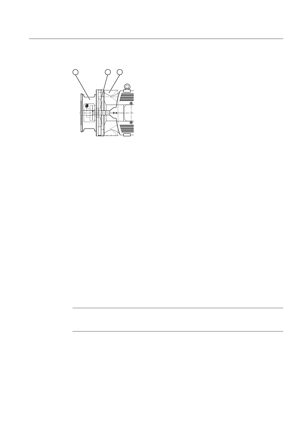
The diagram below shows a gear unit fan:
① Motor bell housing ③ Air guide cover
② Fan
Figure 3-9 Gear unit fan
Further information
Further information and a detailed illustration of the gear unit and the position of the mounted
components can be found in the dimension drawings in the complete documentation for the
gear unit.
3.9.2 Cooling coil
Introduction
The gear unit can be equipped with a cooling coil in the oil sump. The cooling coil is connected
to a cooling water supply. The cooling water connection must be provided by the operator. The
cooling water can be fresh water, sea water or brackish water.
Principle of operation
Heat from the gear unit oil is transferred to the cooling water as it ows through the cooling coil.
Note
To prevent the formation of condensation, make sure that the cooling coil is fully immersed in
the oil.
Improper use can damage the cooling coil. Be sure to take the following precautions:
• Make sure that the cooling water pressure does not exceed 8 bar.
The direction of water ow through the gear unit is optional.
• Make sure that the ends of the cooling coil are not twisted and that the reducer screws are
not removed.
Description
3.9 Cooling
Assembly and operating instructions A5051en
Edition 06/2020 35
 Loading...


