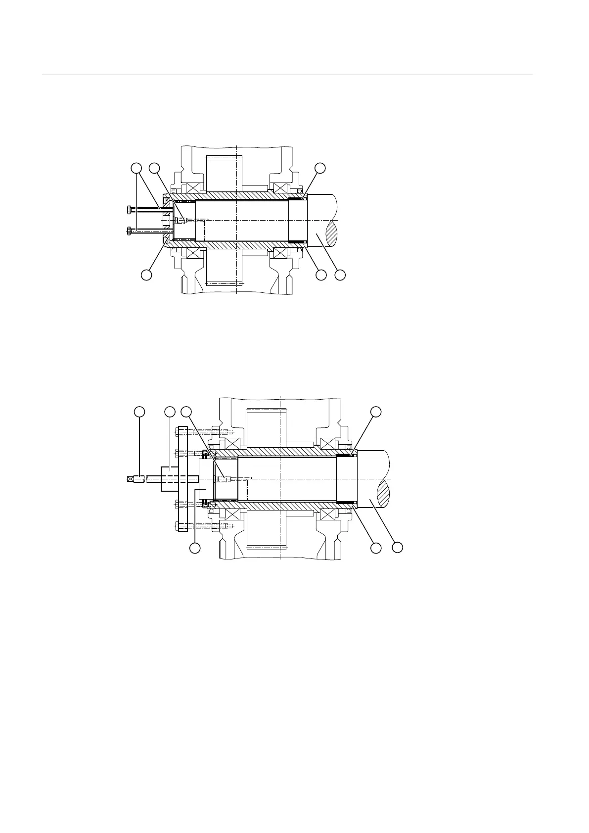
The following diagram shows the dismantling procedure using an end plate for gear units with
a hollow shaft and spline:
① Jacking screws ④ Machine shaft
② Pressure oil connector ⑤ Hollow shaft
③ DU bushing ⑥ End plate
Figure 5-12 Dismantling procedure with end plate for gear units with hollow shaft and spline:
The following diagram shows the dismantling procedure using hydraulic pulling equipment for
gear units with hollow shaft and spline:
① Screw spindle ⑤ Machine shaft
② Hydraulic pulling equipment ⑥ Hollow shaft
③ Pressure oil connector ⑦ Auxiliary plate for pressing out
④ DU bushing
Figure 5-13 Dismantling using hydraulic pulling equipment for gear units with hollow shaft and spline
Assembly
5.5 Shaft-mounted gear unit with hollow shaft and spline according to DIN 5480
Assembly and operating instructions A5051en
80 Edition 06/2020

 Loading...


