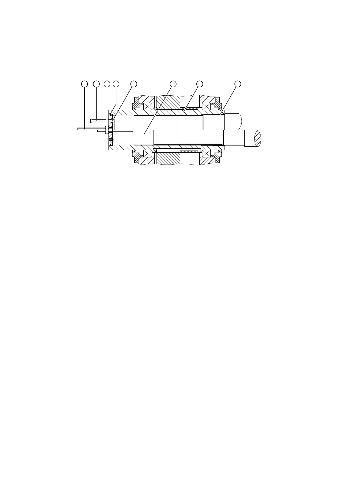
The following diagram shows the preparation for gear units with hollow shaft and shrink disk:
① Screw spindle ⑤ End plate
② Jacking screw ⑥ Machine shaft
③ Nut ⑦ Hollow shaft
④ Locking ring ⑧ DU bushing
Figure 5-14 Preparation for gear units with hollow shaft and shrink disk
Parts 1, 2 and 3 are not included in the scope of delivery.
5.6.1.2 Axial locking
Tightening the shrink disk as per specication ensures that the gear unit is properly axially
locked. It is not necessary to install any further axial locking elements.
5.6.2 Dismantling the shaft-mounted gear unit
Procedure
1. Dismantle the shrink disk.
2. Lift the gear unit o the machine shaft using jacking screws until the seats under the shrink
disk and the DU bushing are exposed.
3. Use suitable hoisting gear to lift the gear unit o the machine shaft.
Assembly
5.6 Shaft-mounted gear unit with hollow shaft and shrink disk
Assembly and operating instructions A5051en
84 Edition 06/2020

 Loading...


