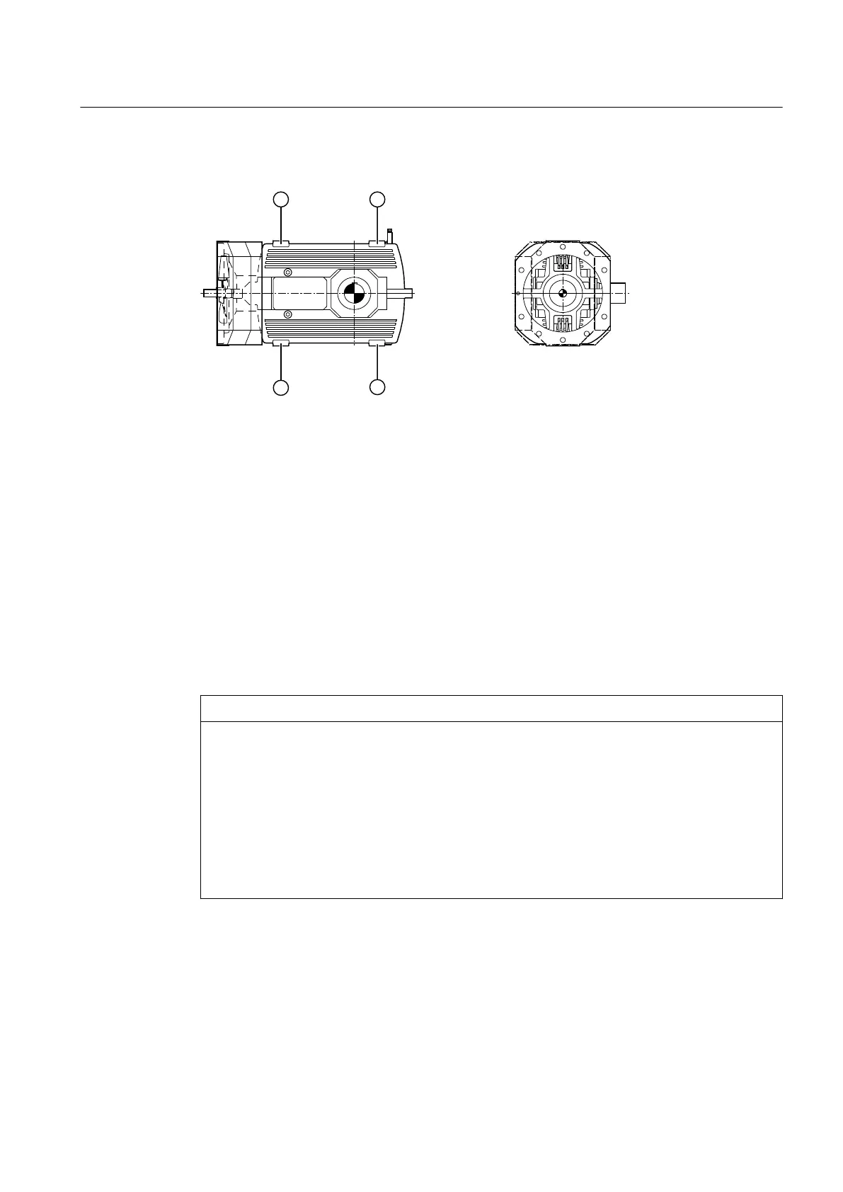
The diagram below shows the alignment surfaces on type B3.. gear units:
① Alignment surfaces
Figure 5-2 Alignment surfaces on type B3.. gear units
5.3.1.2 Mounting on a gear unit swing base
Assembling gear units with baseboards
Use of incorrect attachment points
Use of incorrect attachment points may result in damage to the gear unit. When transporting the
gear unit, only attach it at the lifting eyes provided for the purpose.
The threads in the end faces of the shaft ends may not be used for attaching lifting equipment.
Lifting equipment must be adequately designed to accommodate the weight of the gear unit.
NOTICE
Poor stability
Damage to the gear unit is possible if it is not mounted on a stable foundation.
The gear unit swing base must be absolutely horizontal and at.
It is particularly important that the surface on which the gear unit is mounted is level because
this determines the contact pattern of the teeth and the load on the bearings, and so has an
inuence on the service life of the gear unit.
All points on the gear unit mounting surface must lie between two imaginary parallel planes
that are 0.1 mm per 1 m apart.
Procedure
To mount a gear unit with baseboards on a gear unit swing base, proceed as follows:
1. Clean the underside of the gear unit baseboards and the swing base.
2. Using a suitable crane or lifting gear, place the gear unit down on the gear unit swing base.
Assembly
5.3 Gear unit assembly
Assembly and operating instructions A5051en
Edition 06/2020 67
 Loading...


