3. Tighten the foot fastening bolts with the specied tightening torque (Page 90). If necessary,
install stops to prevent displacement.
4. Align the gear unit precisely with the input and output equipment (Page 66).
5. Record the alignment dimensions.
6. Keep the report in a safe place together with these operating instructions.
NOTICE
Damage caused by unevenly tightening the fastening bolts
The gear unit can be damaged by unevenly tightening the fastening bolts.
Evenly tighten the fastening bolts. When tightening the fastening bolts, make sure that the
gear unit is free of mechanical stress.
Bracing for gear unit swing base
NOTICE
Damage to the gear unit due to incorrectly mounting the motor and gear unit swing base
Damage to the gear unit due to incorrectly mounting the motor and gear unit swing base is
possible.
The motor and swing base may only be mounted after prior consultation with Flender. The
torque arm must be attached on the machine side without resulting in any distortion or
deformation.
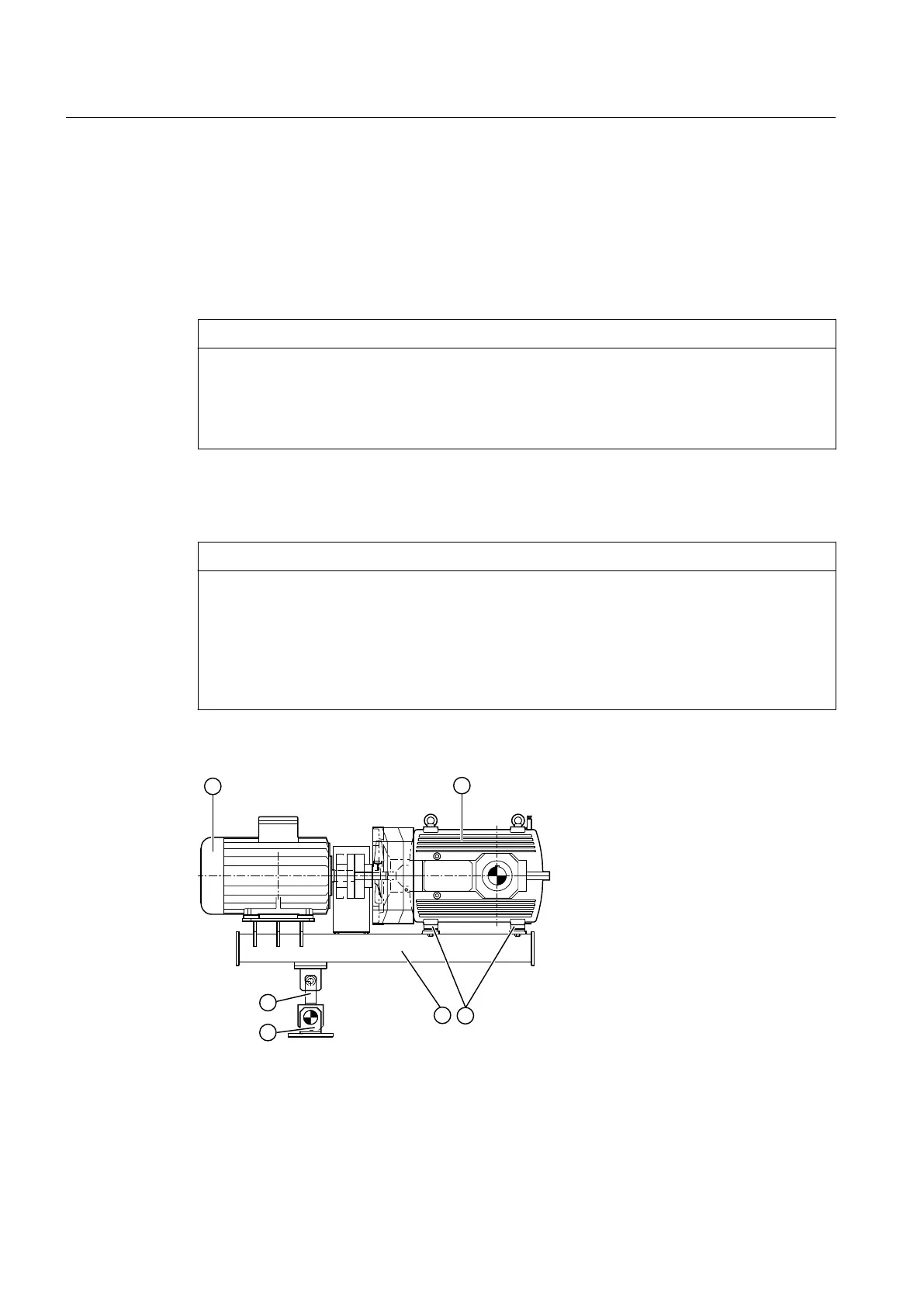
The following diagram shows the torque arm for gear unit swing bases:
① Motor ④ Gear unit swing base
② Gear unit ⑤ Elastic pedestal
③ Baseboards ⑥ Torque arm
Figure 5-3 Gear unit swing base
Assembly
5.3 Gear unit assembly
Assembly and operating instructions A5051en
68 Edition 06/2020
 Loading...


