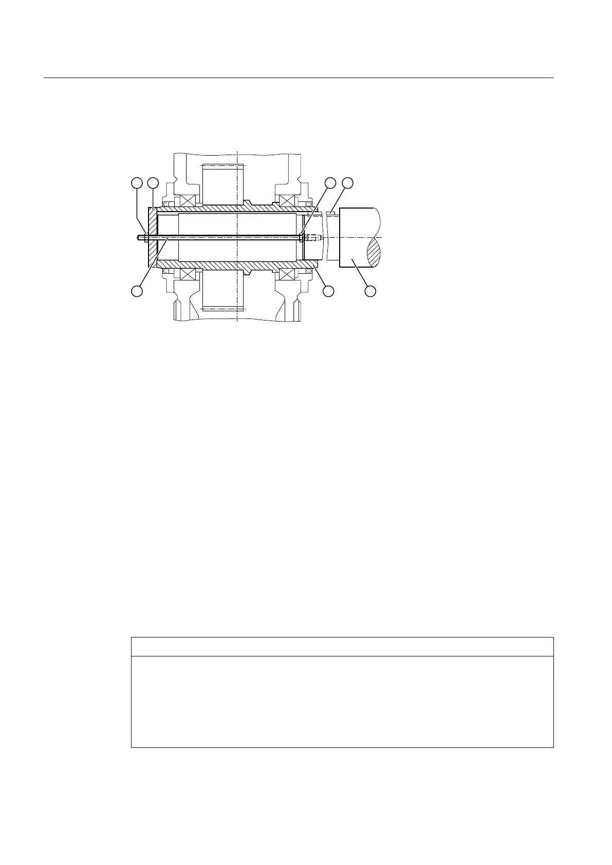
The diagram below shows the mounting process with screw spindle for gear units with a hollow
shaft and parallel keyway:
① Nut ⑤ Machine shaft
② End plate ⑥ Hollow shaft
③ Nut ⑦ Screw spindle
④ Parallel key
Figure 5-6 Screw spindle for gear units with hollow shaft and parallel keyway
Special aspects of shaft-mounted gear units with hollow shaft and parallel keyway
Hydraulic pulling equipment can be used instead of the nut and screw spindle shown in the
diagram.
5.4.2.3 Axial locking
Depending on the version, the hollow shaft must be locked axially on the machine shaft (e.g. by
a locking ring, end plate, adjusting screw).
5.4.3 Dismantling
Measures prior to dismantling
NOTICE
Damage to the gear unit
The gear unit can become damaged if it skews during dismantling.
Do not allow the gear unit to skew as you remove it from the machine shaft. When removing
the gear unit using hydraulic pulling equipment, excessive force can be placed on the housing,
bearings and other gear unit components. Always check the hollow shaft bearings for damage
before reattaching the gear unit to the machine shaft.
Assembly
5.4 Shaft-mounted gear unit with hollow shaft and parallel keyway
Assembly and operating instructions A5051en
72 Edition 06/2020
 Loading...


