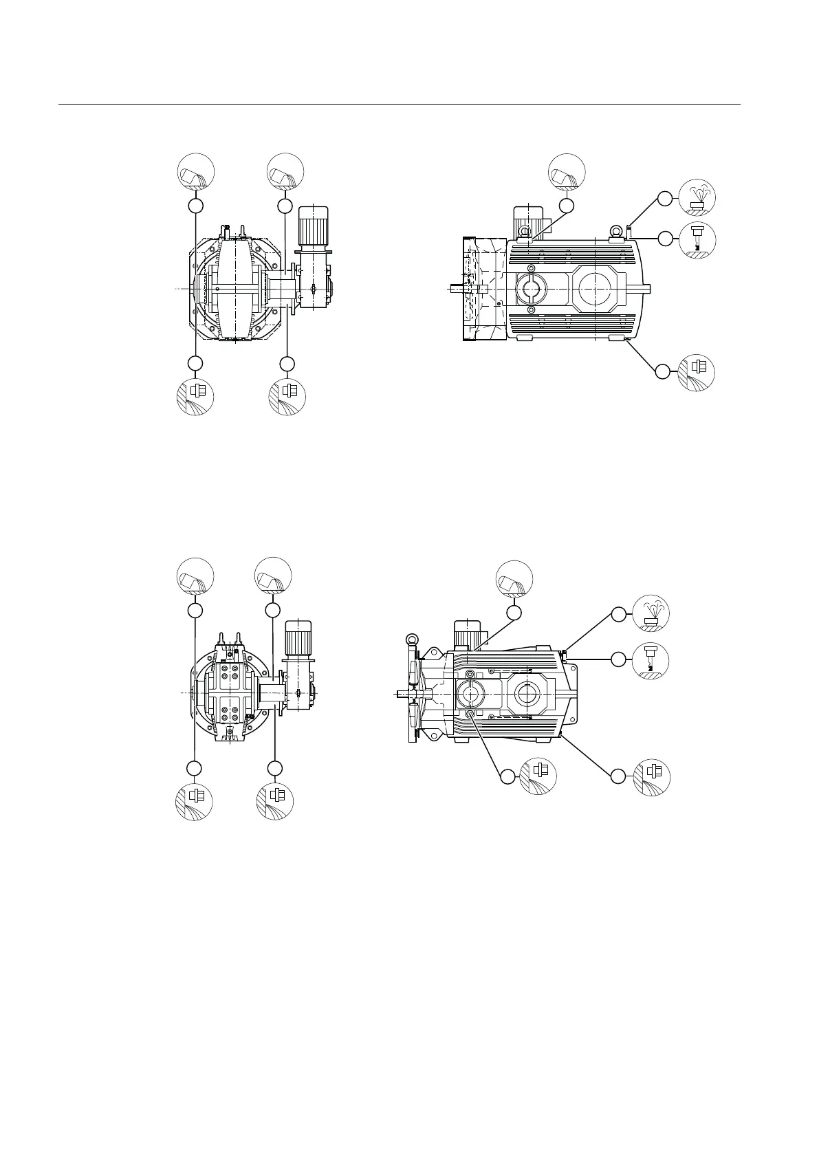
① Oil lling point (backstop) ④ Venting screw or air lter (screw plug)
② Oil lling point (auxiliary gear unit) ⑤ Oil dipstick
③ Oil lling point (main gear unit) ⑥ Oil drain screw
Figure 4-11 Oil lling points and oil draining points on type B3.A gear units with auxiliary drive
The diagram below shows the oil lling points and the oil draining points on a type B3SF gear
unit with auxiliary drive:
① Oil lling point (backstop) ④ Venting screw or air lter (screw plug)
② Oil lling point (auxiliary gear unit) ⑤ Oil dipstick
③ Oil lling point (main gear unit) ⑥ Oil drain screw
Figure 4-12 Oil lling points and oil draining points on type B3SF gear units with auxiliary drive
Further information
Further information, a detailed illustration of the gear unit and the position of the mounted
components can be found in the dimension drawing in the complete documentation for the
gear unit.
Application planning
4.4 Special aspects of gear unit lubrication and preservation
Assembly and operating instructions A5051en
58 Edition 06/2020