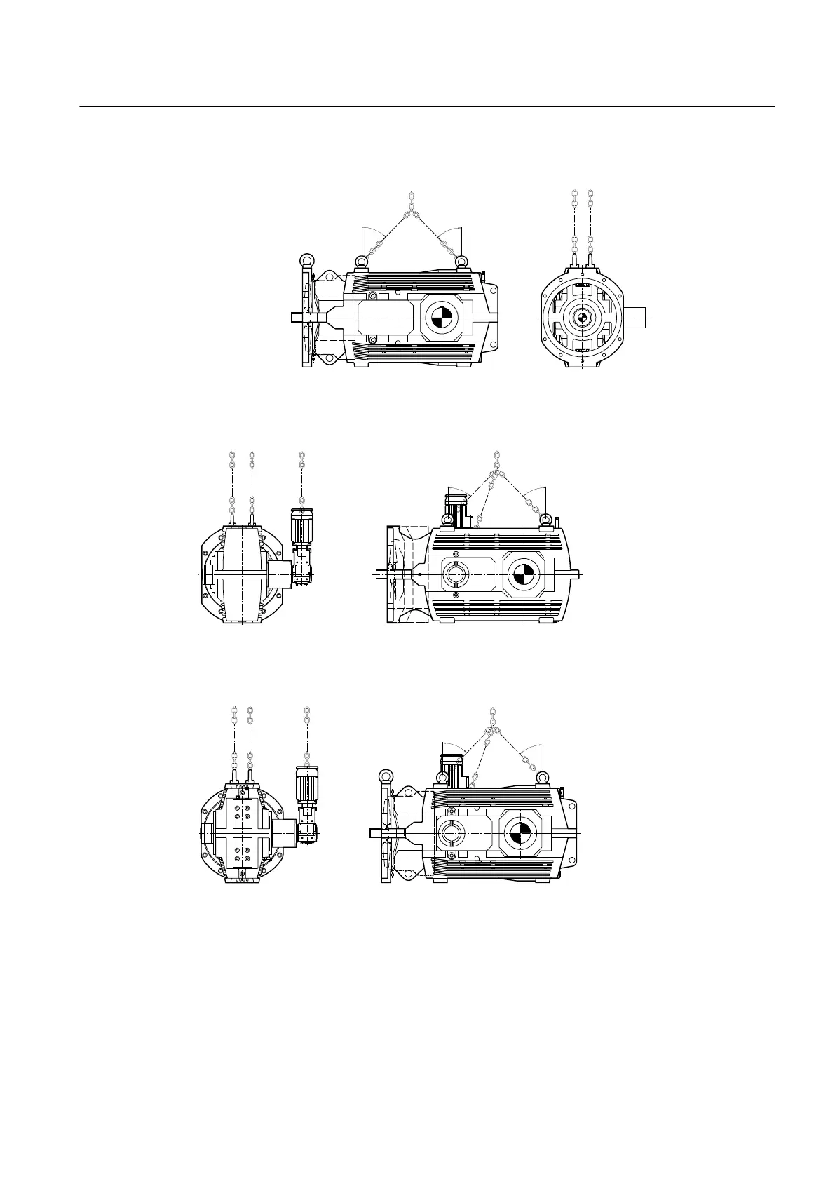
The diagram below shows the position of the attachment points on type B3SF gear units:
Figure 4-4 Attachment points and pulling direction on type B3SF gear units
The diagram below shows the position of the attachment points on type B3.A gear units with
auxiliary drive:
Figure 4-5 Attachment points and pulling direction on type B3.A gear units with auxiliary drive
The diagram below shows the position of the attachment points on type B3SF gear units with
auxiliary drive:
Figure 4-6 Attachment points and pulling direction on type B3SF gear units with auxiliary drive
The diagram below shows the position of the attachment points on type B3.A gear units with
motor:
Application planning
4.3 Attachment points
Assembly and operating instructions A5051en
Edition 06/2020 55

 Loading...


