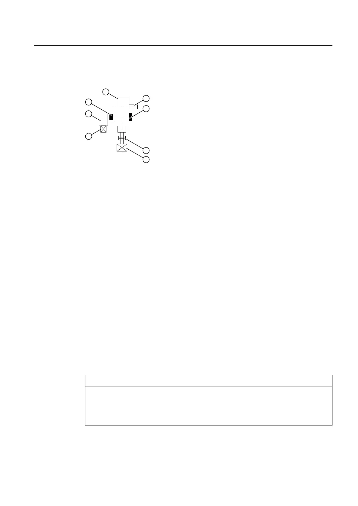
The basic conguration of the gear unit with main and auxiliary drive is shown in the following
diagram.
① Main gear unit ⑤ Main motor
② Output shaft of the main gear unit ⑥ Auxiliary motor
③ Backstop ⑦ Auxiliary gear unit
④ Coupling ⑧ Overrunning clutch
Figure 3-18 Gear unit with main and auxiliary drive
Depending on the particular application, two auxiliary drives with two dierent ratings are
available for each gear unit size.
Further information
You can nd further information, a detailed illustration of the gear unit and the position of the
auxiliary drive in the dimension drawing in the complete gear unit documentation.
3.19.1 Auxiliary drive, designed as maintenance drive
Auxiliary drive
The auxiliary drive motor is dimensioned so that it is possible to operate the conveyor system
under no-load conditions at low speeds in the same direction of rotation.
The auxiliary drive is anged to the main gear unit through an intermediate ange. The auxiliary
drive is a bevel geared motor that is coupled to the main gear unit via an overrunning clutch. The
overrunning clutch is accommodated in the intermediate ange, and is supplied with oil from
the main gear unit. The auxiliary drive has its own oil.
NOTICE
Overload of the auxiliary drive
Destruction or damage of the auxiliary drive as a result of overload.
The conveyor system may only be driven by the auxiliary drive when operating under no-load
conditions.
Description
3.19 Auxiliary drive
Assembly and operating instructions A5051en
Edition 06/2020 45

 Loading...


