Threaded holes at the face sides of gear unit hollow shafts
Refer to the following table for the dimensions of the threaded holes at the face sides of gear unit
hollow shafts:
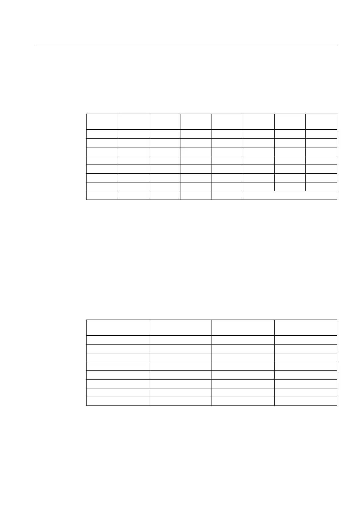
Table 5-1 Dimensions for the threaded holes at the face sides of gear unit hollow shafts
Gear unit
size
m in mm s t in mm Gear unit
size
m in mm s t in mm
4 95 M8 14.5 12 215 M12 19.5
5 115 M8 14.5 13 230 M12 19.5
6 125 M8 14.5 14 250 M12 19.5
7 140 M10 17 15 270 M16 24
8 150 M10 17 16 280 M16 24
9 160 M10 17 17 300 M16 24
10 180 M12 19.5 18 320 M16 24
11 195 M12 19.5 ≥ 19 On request
Improper use can damage the gear unit. Be sure to take the following precautions:
• When removing a gear unit that is not only supported at the hollow shaft, but also at the
housing, ensure that the specied forcing pressures are not exceeded.
• Always check the hollow shaft bearings for damage before reattaching the gear unit to the
machine shaft.
• When using jacking screws or screw spindles, to avoid the risk of corrosion, round-o and
grease the end of the thread that presses against the driven machine.
Maximum forcing pressures
Refer to the following table for the maximum forcing pressures:
Table 5-2 Maximum forcing pressures
Gear unit size Maximum forcing
pressures in N
Gear unit size Maximum forcing
pressures in N
4 22 600 12 113 600
5 33 000 13 140 000
6 37 500 14 160 000
7 50 000 15 193 000
8 56 000 16 215 000
9 65 000 17 240 000
10 82 000 18 266 000
11 97 200 ≥ 19 On request
Assembly
5.4 Shaft-mounted gear unit with hollow shaft and parallel keyway
Assembly and operating instructions A5051en
Edition 06/2020 75

 Loading...


