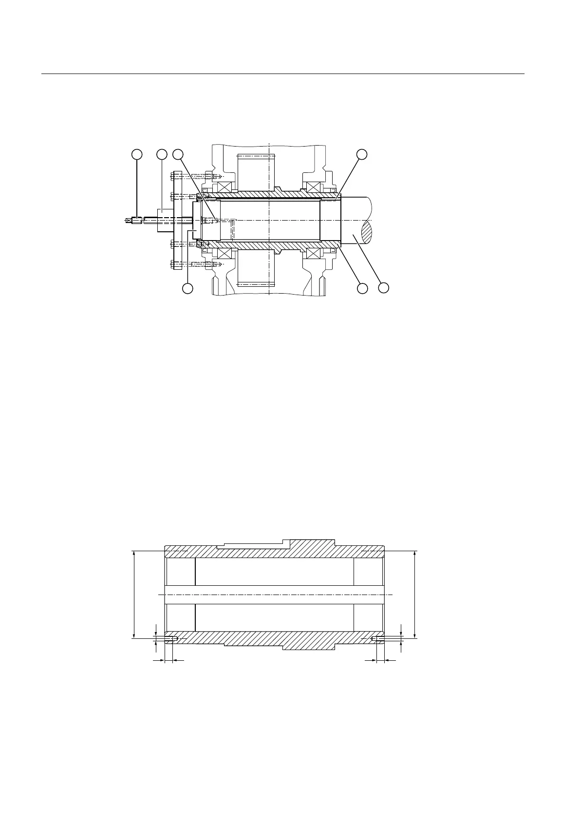
The following diagram shows the dismantling procedure using hydraulic pulling equipment for
gear units with hollow shaft and parallel keyway:
① Screw spindle ⑤ Machine shaft
② Hydraulic pulling equipment ⑥ Hollow shaft
③ Pressure oil connector ⑦ Auxiliary plate for pressing out
④ Parallel key
Figure 5-8 Dismantling using hydraulic pulling equipment
End plate and auxiliary plate
The end plate and auxiliary plate for removing the gear unit are not supplied as standard with
the gear unit. Both end faces of the hollow shaft have threaded holes for attaching the end plate
to the shaft.
Further information
Further information and a detailed illustration of these threaded holes can be found in the
dimension drawing in the complete documentation for the gear unit.
The following diagram shows a hollow shaft with parallel keyway:
Figure 5-9 Hollow shaft with parallel keyway
*) 2 threads oset through 180 °
Assembly
5.4 Shaft-mounted gear unit with hollow shaft and parallel keyway
Assembly and operating instructions A5051en
74 Edition 06/2020
 Loading...


