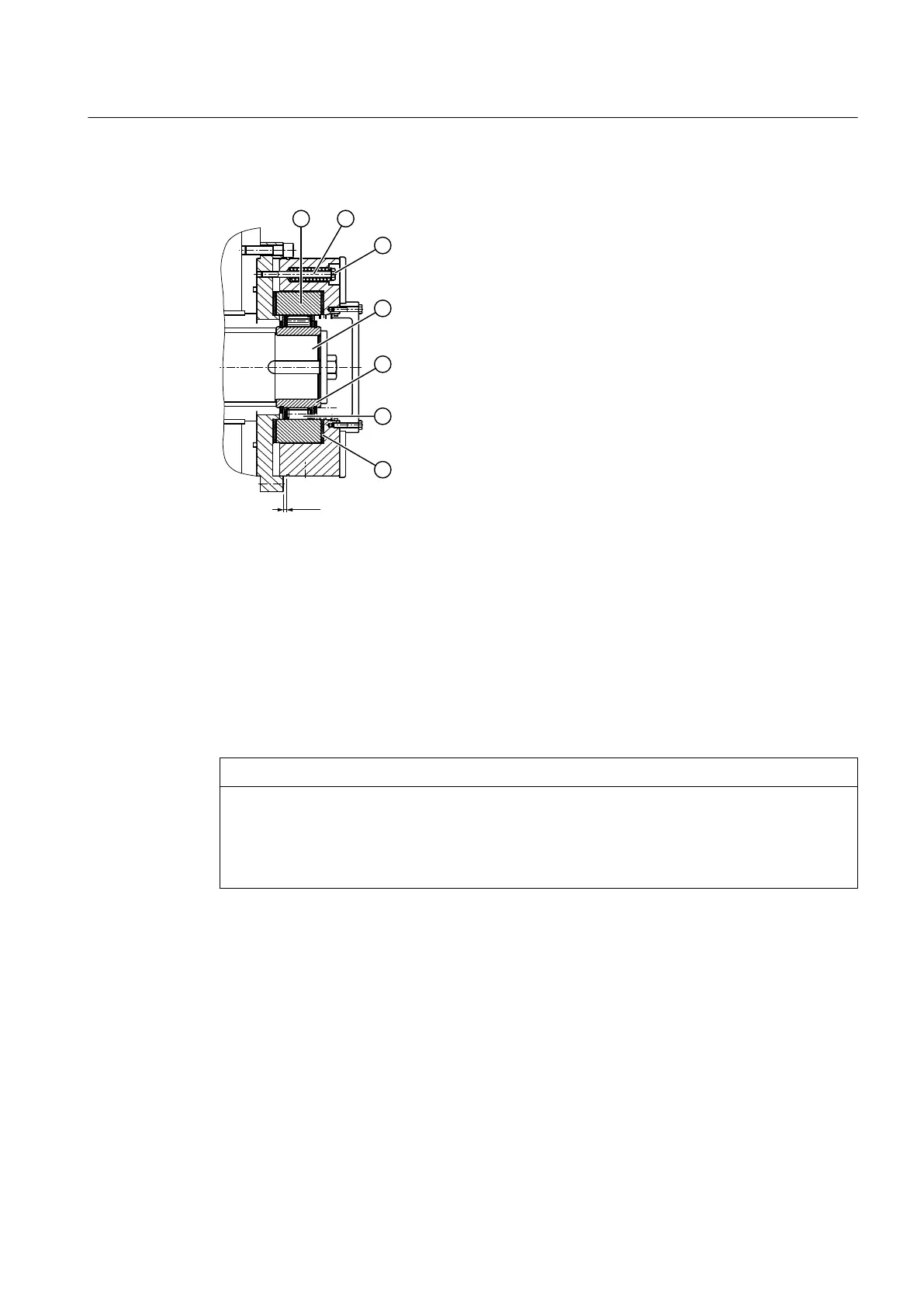
The following diagram shows a torque-limiting backstop:
① Outer ring ⑤ Inner ring
② Guide screw with spring ⑥ Cage with sprags
③ Locking wire ⑦ Friction lining
④ Shaft (intermediate ange)
Figure 3-8 Torque limiting backstop
Before connecting the motor, identify the phase sequence of the three-phase mains using a
phase sequence instrument. Connect the motor corresponding to the dened direction of
rotation.
You can change the blocking direction of the backstop by turning over the cage. You must always
contact Flender in advance if you wish to change the blocking direction.
NOTICE
Damage to the backstop and gear unit due incorrect direction of rotation
Damage to the backstop and gear unit due incorrect direction of rotation possible.
Do not operate the motor adversely to the blocking direction of the gear unit. Observe the note
attached to the gear unit.
Sliding torque
The torque limiting backstop is mounted to the gear unit through an intermediate ange
creating an oil tight seal; the backstop is integrated in the gear unit oil circuit.
The guide screws of the springs are locked using locking wire so that the slip torque that has been
adjusted cannot be changed. The warranty is null and void if the locking wire for the screws is
either missing or damaged.
Generally, the backstop operates without any wear. As a preventive measure, dimension "x
min.
"
should be checked each time that the backstop is actuated (only type FXRT) - and then it should
be checked every 12 months.
Description
3.8 Torque limiting backstop (special version)
Assembly and operating instructions A5051en
Edition 06/2020 33
 Loading...


