Gear unit equipment with auxiliary drive
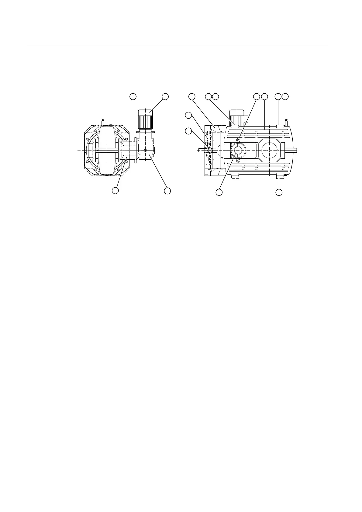
The diagram below shows the gear unit equipment on type B3.. gear units:
① Speed monitoring ⑧ Baseboards (mounted components)
② Electric motor ⑨ Backstop
③ Air guide cover ⑩ Shaft seal
④ Threads for transport lugs ⑪ Fan
⑤ Alignment surfaces ⑫ Auxiliary gear unit
⑥ Inspection hole ⑬ Overrunning clutch
⑦ Main gear unit
Figure 3-20 Gear unit equipment on type B3.. gear units
Further information
You can nd further information, a detailed illustration of the gear unit and the position of the
auxiliary drive in the dimension drawing in the complete gear unit documentation.
You can nd additional information on the auxiliary drive in the auxiliary drive operating
instructions, provided in the complete gear unit documentation.
You can nd the precise designation of the geared motor and the mounting position in the
dimension drawings in the complete gear unit documentation.
3.19.2 Overrunning clutch
If, in addition to the main drive, you couple an auxiliary drive to the gear unit, then this coupling
is realised using an overrunning clutch.
When the auxiliary drive is used to drive the gear unit, the overrunning clutch allows torque to
be transferred in one direction of rotation, while "free-wheeling operation" applies when driven
by the main drive.
The output shaft of the main drive rotates in the same direction of rotation, irrespective of
whether the main drive is used or the auxiliary drive.
Description
3.19 Auxiliary drive
Assembly and operating instructions A5051en
48 Edition 06/2020
 Loading...


