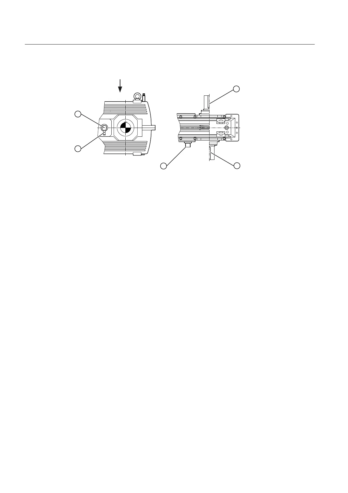
The following diagram shows a speed encoder:
① Incremental speed encoder ③ 12-pole brass connector
② Output
Figure 3-17 Speed encoder
Further information
Further information, a detailed illustration of the gear unit and the position of the mounted
components can be found in the dimension drawing in the complete documentation for the
gear unit.
You can nd further information about the speed encoder (such as control instructions) and
technical data, in the speed encoder operating instructions and in the equipment list provided
in the complete gear unit documentation.
3.19 Auxiliary drive
For specic applications, the gear unit can be equipped with an auxiliary drive. The auxiliary
drive enables the main gear unit to be operated at a lower output speed in the same direction
of rotation. Either Flender or the customer provides the auxiliary drive. The auxiliary drive is
connected to the main gear unit through an overrunning clutch. The auxiliary drive is mounted
onto a connection ange, which in turn is attached to the main gear unit. The overrunning
clutch is located in a separate oil space. The auxiliary drive has its own oil circuit, which is
separate from that of the main gear unit.
Before connecting the motor, identify the phase sequence of the three-phase mains using a
phase sequence instrument. Then connect the motor so that it rotates in the dened direction.
Observe the note attached to the gear unit.
Description
3.19 Auxiliary drive
Assembly and operating instructions A5051en
44 Edition 06/2020
 Loading...


