Figure 4-7 Attachment points and pulling direction on type B3.A gear units with motor
The diagram below shows the position of the attachment points on type B3.A gear units with
gear unit swing base:
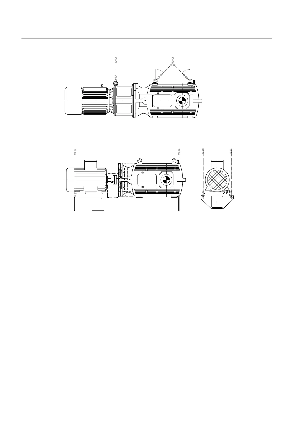
Figure 4-8 Attachment points and pulling direction on type B3.A gear units with gear unit swing base
Drive units with additional components mounted on the gear unit (such as drive motor,
coupling, etc.) may require an extra attachment point owing to the displacement in the centre
of gravity caused by the mounted components.
Further information
Further information, a detailed illustration of the gear unit and the position of the attachment
points can be found in the dimension drawings in the complete documentation for the gear unit.
Application planning
4.3 Attachment points
Assembly and operating instructions A5051en
56 Edition 06/2020

 Loading...


