5.5 Shaft-mounted gear unit with hollow shaft and spline according to
DIN 5480
Introduction
The shaft end of the driven machine must have a spline according to DIN 5480. Furthermore, it
should have a hole centred in its end face as dened by DIN 332, form DS (with thread).
Further information
Further information about the connection dimensions of the driven machine shaft can be found
in the dimension drawing in the complete documentation for the gear unit.
5.5.1 Preparations
To make it simpler to remove (Page 79), we recommend that a pressurised oil connection is
provided in the shaft end of the driven machine, which is drilled through to the recess in the
hollow shaft. This connector can also be used to feed in rust remover.
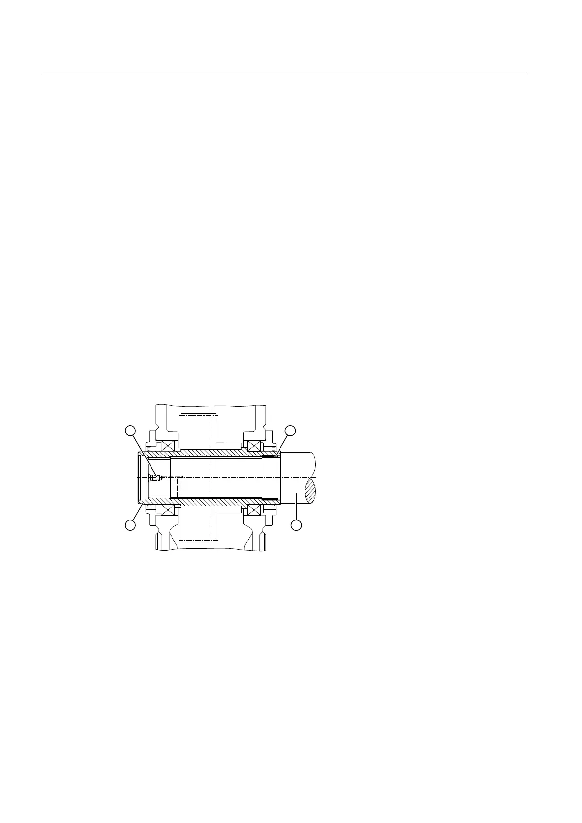
The following diagram shows the preparation for gear units with hollow shaft and spline:
① Pressure oil connector ③ Machine shaft
② DU bushing ④ Hollow shaft
Figure 5-10 Preparation for gear units with hollow shaft and spline
Assembly
5.5 Shaft-mounted gear unit with hollow shaft and spline according to DIN 5480
Assembly and operating instructions A5051en
76 Edition 06/2020

 Loading...


