The lubrication points are designated using the following sign:
RSHUDWLQJKRXUVDIWHU
/XEULFDWLRQSRLQW
JOLWKLXPVRDSEDVHGJUHDVH
Figure 3-2 Sign: Lubrication point
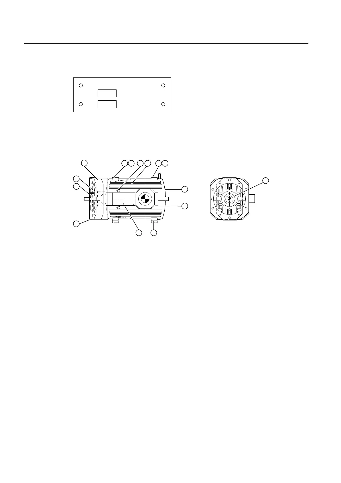
Gear unit equipment
The diagram below shows the gear unit equipment on type B3.. gear units:
① Air guide cover ⑧ Baseboards (mounted components)
② Threads/transport lugs ⑨ Cover
③ Alignment surfaces ⑩ Fastening for torque arm
④ Inspection hole ⑪ Shaft seal
⑤ Housing ⑫ Fan
⑥ Rating plate ⑬ Cover
⑦ Cover
Figure 3-3 Gear unit equipment on type B3.. gear units
Further information
Further information, a detailed illustration of the gear unit and the position of the mounted
components can be found in the dimension drawing in the complete documentation for the
gear unit.
3.4 Oil supply to the gear unit
3.4.1 Dip lubrication
Unless otherwise agreed by contract, the gearing and rolling-contact bearings are supplied with
an adequate quantity of oil by splash lubrication.
Description
3.4 Oil supply to the gear unit
Assembly and operating instructions A5051en
26 Edition 06/2020

 Loading...


