FLUXUS F808, F809 8 Installation of the Transducers
96 UMFLUXUS_F808_8091V1-2-1EN, 2019-08-23
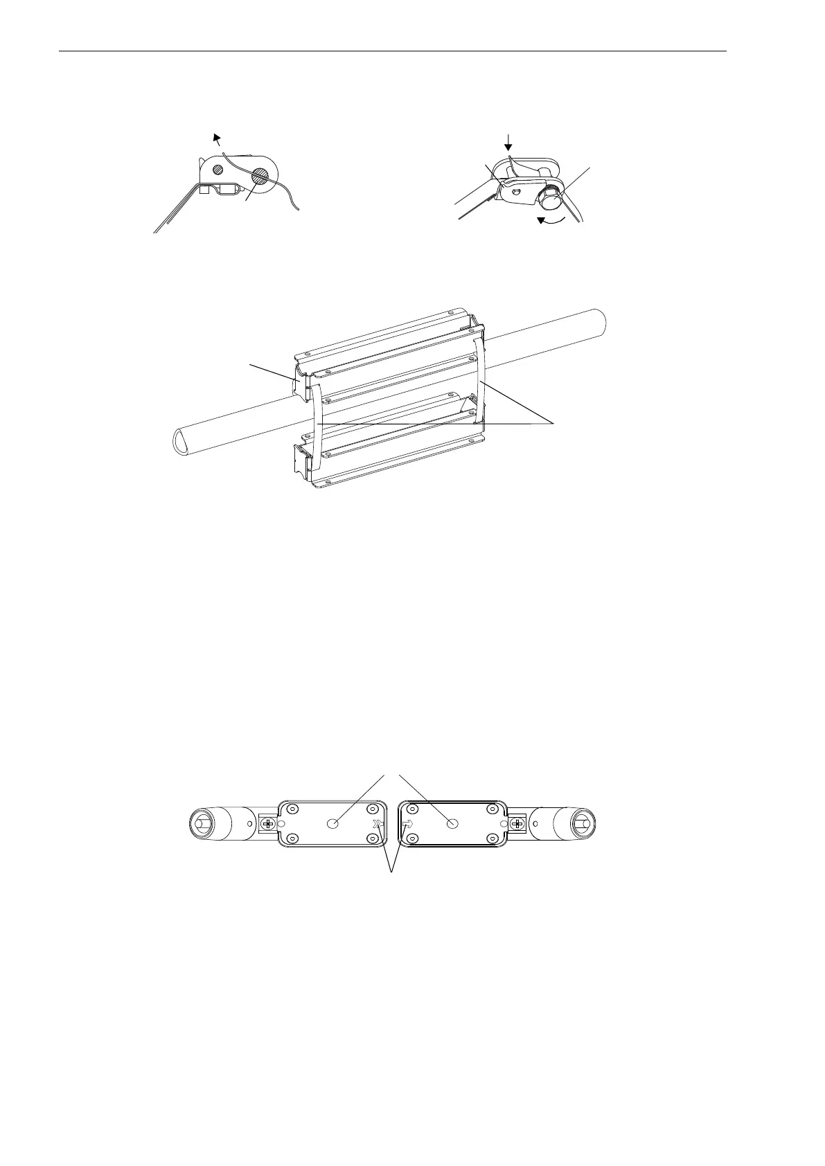
8.5.5 Installation of the transducers
Mount the transducers into the rail in such way that the engravings on the transducers form an arrow (see Fig. 8.53). The
transducer cables show in opposite directions.
• Slide the cover over the rail.
• Insert the transducer with the conduit sealing fitting into the rail. The round cutout of the cover faces the conduit sealing
fitting.
• Observe that there must be no air pockets between the transducer contact surface and the pipe wall.
• Align the transducer with the cover in such way that the hole in the transducer is placed below the tensioning screw.
Use the tensioning screw of the cover to press the transducer against the pipe.
• Screw the flexible conduit (approved for FM Class I, Division 1) onto the transducer with the conduit sealing fittings.
• Repeat the steps for the second transducer.
• Connect the flexible conduit to the conduit system of the facility in accordance with the local regulations.
Fig. 8.51: Ratchet clasp with tension strap
Fig. 8.52: Installation of the rail with tension straps (diagonal arrangement, small transducer distance)
Fig. 8.53: Correct positioning of the transducers
3
lever
sense of rotation
cut
screw of the clasp
tension straps
rail
holes for the screws
engravings
 Loading...


