8 Installation of the Transducers FLUXUS F808, F809
UMFLUXUS_F808_8091V1-2-1EN, 2019-08-23 95
8.5.4 Installation of the rail with tension straps
The number and arrangement of PermaFiX rails depends on the required transducer arrangement and transducer dis-
tance. See Fig. 8.49 for an overview of possible arrangements.
• Select the arrangement according to the measurement.
• Disassemble the transducer mounting fixture PermaFiX (see Fig. 8.45).
• Cut the tension straps to length (pipe circumference + at least 120 mm).
• Insert approx. 100 mm of the tension strap into part 1 and 2 of the clasp (see Fig. 8.50 a).
• Bend the tension strap.
• Insert the tension strap into part 1 of the ratchet clasp (see Fig. 8.50 b).
• Tighten the tension strap.
• Insert the tension strap into the slots of one rail (arrangements b, c, d) or both rails (arrangement a) (see Fig. 8.52).
• Place the rail with the tension strap on the pipe and the tension strap around the pipe (arrangements b, c, d) or place
the two rails with the tension strap around the pipe (arrangement a).
• Insert the free end of the tension strap into part 3 of the ratchet clasp (see Fig. 8.51).
• Tighten the tension strap.
• Cut off the protruding tension strap (see Fig. 8.50).
• Tighten the screw of the ratchet clasp.
• Repeat the steps for the second tension strap.
• Repeat the steps for the second rail, if necessary.
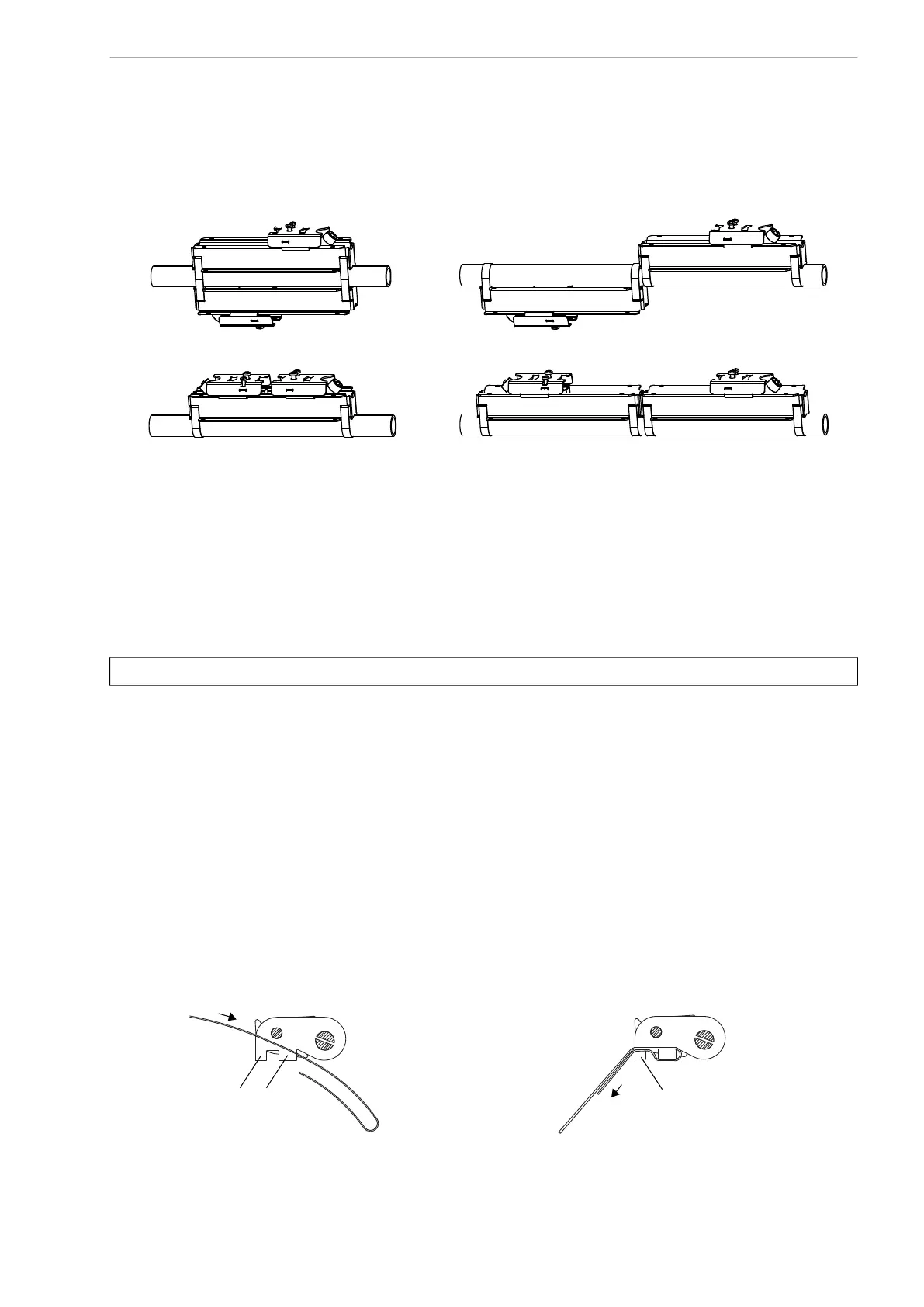
Fig. 8.49: Possible arrangements of PermaFiX (installation with tension straps)
a – diagonal arrangement, small transducer distance
b – reflection arrangement, small transducer distance
c – diagonal arrangement, large transducer distance
d – reflection arrangement, large transducer distance
Attention! The edge of the tension strap is very sharp, leading to risk of injury. Debur sharp edges.
a b
Fig. 8.50: Ratchet clasp with tension strap
a
b
c
d
1 2
1

 Loading...


