Limitorque
®
MX Electronic Actuator FCD LMENIM2306-09-AQ – 08/17
26
Particular care should be taken when terminating twisted-pair shielded cables in a control network. Avoid nicks, cuts, or
abrasions in the insulation of data communication cables, since this may result in inadvertent ground connection. Also,
excess cable should be cut, not coiled or looped, to prevent noise induction into the network.
Limitorque strongly recommends remote communication wiring be routed separately from mains line power wiring.
Specifically, instrumentation wiring, including communication, analog and discrete signal wiring, should be routed
in conduit that is separated from power lines. If the recommendation is not followed, the intergrity of instrumenta-
tion signals may be comprimised. If the signal is comprimised, the MX will enter a“safe-state” whereby all motion is
prohibited until communication is sucessfully re-established.
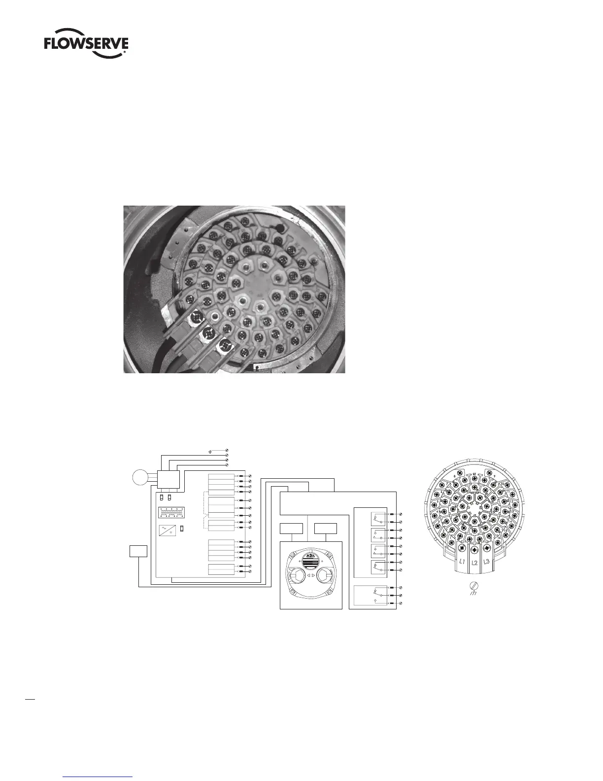
Figure 3.13 – View of terminal block
Figure 3.14 – Standard wiring diagram illustrating 3 phase motor voltage applied.
NOTE: Most current wiring diagram is shipped within the terminal compartment of the MX.
Cable Preparation
Prepare the network cable for connection to the MX actuator terminal block as illustrated in Figures 3.15 through 3.18.
a
CAUTION: Strip stranded conductors carefully; do not damage the strands. This will weaken the conductor.
Do not nick conductors when stripping away the insulation. Nicking stresses the conductor and can cause the
conductor to break. This type of damage may not be apparent and failure can occur later without warning.
Configurable SET-UP to give;
Either
-Contact closed-Valve OPEN S
-Contact opened-Valve CLOSE
OR :
-Contact closed-Valve CLOSES
-Contact opened-Valve OPEN S
3-WIRE 4-WIRE
INHIBIT ESD
5
7
5
6
7
9
10
21
INTERNAL
SUPPLY
110V AC
8
5
7
12
8
11
5
6
7
8
12
8
11
5
7
13
8
14
5
6
7
13
8
14
8 8
9
10
21
12 12
9
10
21
13 13
8
14
8
14
5
CLOSE
STO P
6
OPEN
7
CONTROL COMMON
8
11
0V AC
110V AC
12
+24V DC
13
0V DC
14
10
OPEN INHIBIT
CLOSE INHIBIT
9
ESD
21
FUNCTIO N
POIN T
TERMINAL
EXTERNAL
SUPPLY
24 TO 110
VOLT
AC/D C
8
11
8
11
AC/DC
0V
AC/D C
24-110V
AC/D C
0V
AC/DC
24-110V
AC/D C
0V
AC/D C
24-110V
AC/D C
0V
AC/DC
24-110V
EXTERNAL SUPPLY
Configurable SET-UP to give;
Either
-OPEN/CLOSE push-to-run
(inching) mode OR
-OPEN/CLOSE push and release
(maintained) mode with mid-
travel reversal
(Stop before reverse)
mid-travel stop
reversal and
with mid-travel
(maintained) MODE
Push-and-release
OPEN/STOP/CLOSE
close contacts
maintained open or
interlock/inhibit on
SET-UP to give;
Configurable during
CLOSED/OPEN/STOP/IGNORED
maintained ESD signal:
ACTIONS on receipt of a
to give following modes of
Configurable during SET-U P
REMOTE WIRING CONNECTIONS
7
8
2-WIRE
7
12
8
11
7
13
8
14
AC/D C
0V
AC/D C
24-110V
OUTPUT SWITCH CONTACT DEVELOPMENT
VALVE POSITIO N
FULL
CLOSE
FULL
OPEN
FUNCTIO N
CLOSE LIMIT
AS4
OPEN LIMIT
AS 3
CLOSE LIMIT
OPEN LIMIT
AS1
AS2
SWITCH
OUTPU T
INTERNAL
SUPPLY
24V DC
Grounding lug
View of terminal block
Reversing
contactor
Close
Stop
Open
Dig Com #1-Ve
Close inhibit/
interlock Input 1
interlock Input 2
Open inhibit/
Dig Com #2-Ve
0 VAC
110 VAC
24 VDC +Ve
0 VDC
24 VDC +Ve
0 VDC
27
26
25
35
28
29
34
24
23
21
22
7
6
L1
L2
L3
FS1 FS2
FS3
LimiGard
Motor
board
Power
PE
Three-phase supply
Control
supply
Aux.
input
(Optional)
*
E.S.D. Input 0
Dig Com #3-Ve
32
30
Position
sensor
44
45
48
49
46
47
50
51
S1a
S1b
S2a
S2b
“ CLOSE ”
position
“ OPEN ”
position
54
53
52
Show n
with
power
supply off
Control panel
Torque
sensor
Monitor relay
Circuit shown with valve in fully
closed position and with power off.
Main processor board
Status feedback
output switches
Default setting
“ CLOSE ”
position
“ OPEN ”
position
CLOSE
STOP
OPEN
(YES)
REMOTE
LOCAL
(NO)
Limitorque
*
Jumpers may be added to connect digital commons - pt. 28 & 29, 31& 32
Note: 110 VAC control supply from actuator is optional.
LMENIM2306-09 AQ.indd 26 Mittwoch23.08.17 08:53