E018-P
Page 44 FW_E018-P_M_v0302-02_EN
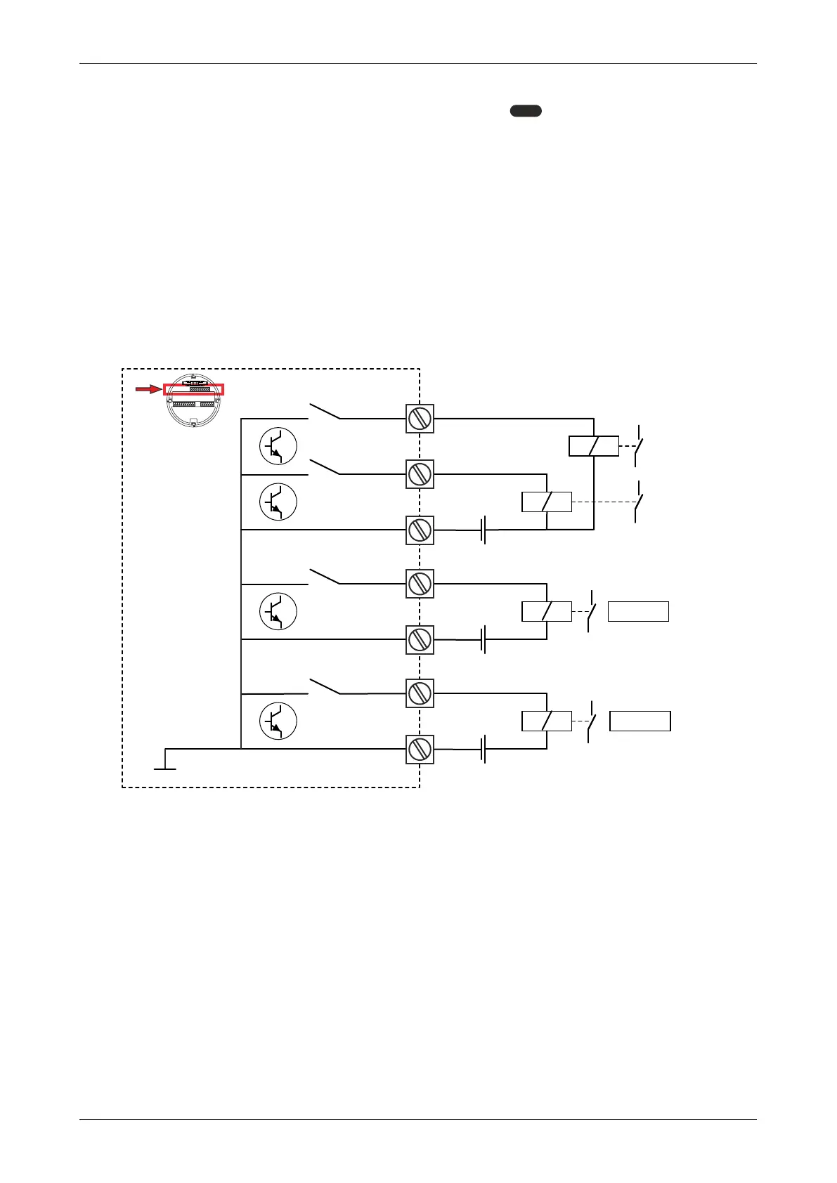
6.4.9 TERMINALS R1-R7 AND R8-R11: DIGITAL OUTPUTS D1-D4 AND D5-D6
The functionality of the digital output is programmed through
8: RELAY OUTPUTS[»28].
● The digital outputs D1 and D2 have a maximum frequency of 500Hz for scaled pulse, 4Hz for
alarms and 10kHz for pulse retransmission.
● When retransmit mode is selected, output D1 retransmits the flowmeter signal.
● The digital outputs D3 and D4 have a maximum frequency of 4Hz.
● The optional digital outputs D5 and D6 have a maximum frequency of 0.5Hz and follow the
functionality selected for output D3 and D4, respectively.
Type OT
Four passive transistor outputs are available, two with a maximum frequency of 500Hz (D1 and D2)
and two with a maximum frequency of 4Hz (D3 and D4). Each has a maximum driving capacity of
300 mA, 50 VDC.
● Terminals R1, R3 and R5 are common ground (GND) terminals.
● When retransmit mode is selected the maximum frequency for D1 is 10kHz with a 50% duty
cycle and a minimum on and off- time of 50µs.
R1
R2
+
123 5674123 5674
R3
R4
+
D2
D1
123 5674123 5674
Common system ground
R5
+
D3
R6
R7
D4
N O. .
N O. .
N O. .
N O. .
MEM
Fig.29: Terminals R1-R7: Transistor outputs D1 – D4
Type OR
Two mechanical normally open relay outputs (D5 and D6) are available with a maximum frequency
and switching power of 0.5 Hz, 250VAC/30VDC, 1A resistive / 0.5 A inductive. With Type OR:
● Use power supply terminals P5-P6. Required supply voltage is 24 – 27VDC.
● Be sure that the output frequency does not exceed 0.5Hz, else the relay lifetime and reliability
will be reduced significantly.
● The functionality of output D5 and D6 corresponds with the functionality of digital outputs D3 and
D4, respectively.