E018-P
FW_E018-P_M_v0302-02_EN Page 45
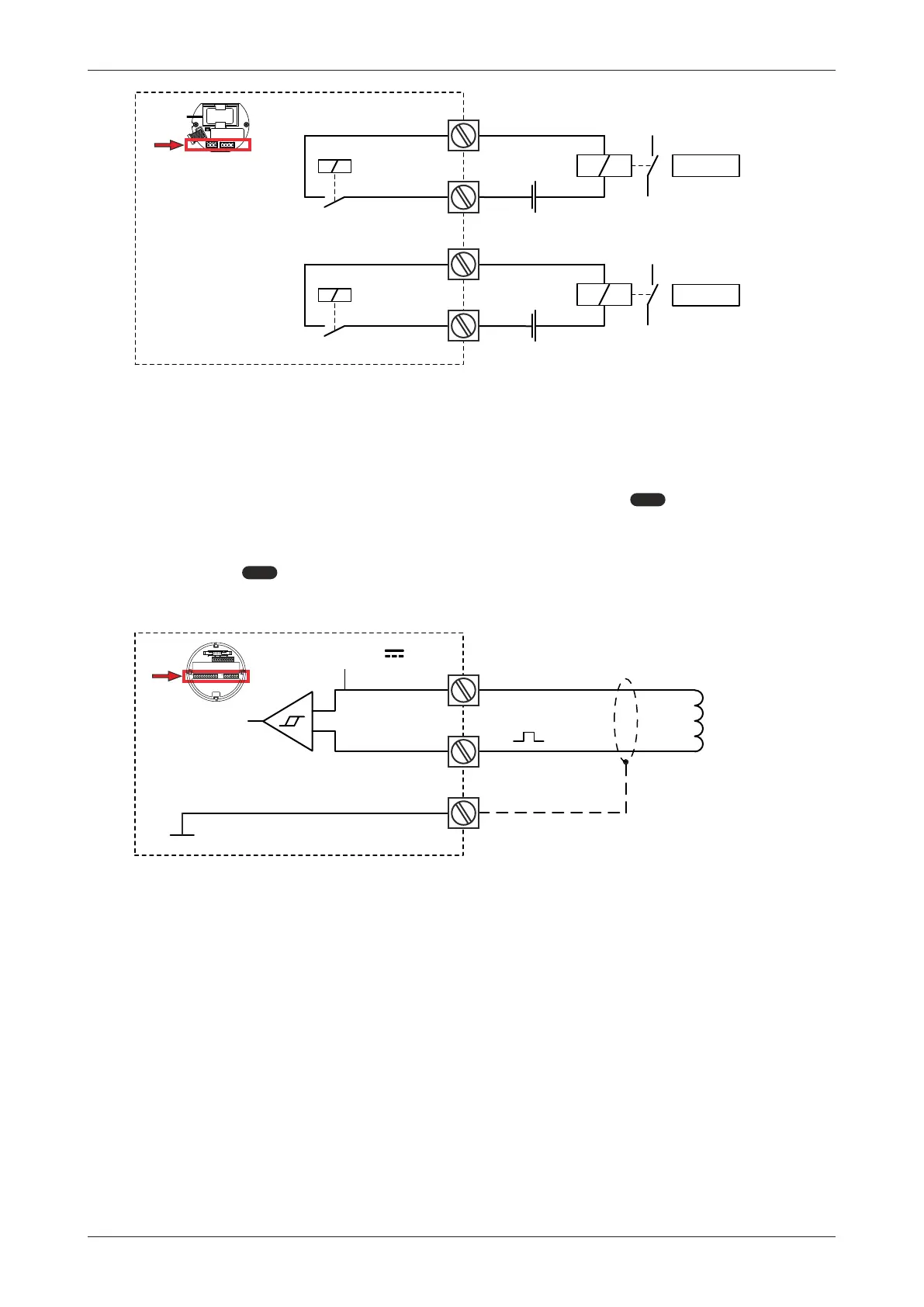
R8
R9
+
N O. .
D6
R10
R11
+
N O. .
D5
RSM
1234567
Max. 0,5Hz
1234567
Max. 0,5Hz
Fig.30: Terminals R8-R11: Mechanical relay outputs D5-D6
6.4.10 TERMINALS S1-S3: FLOWMETER INPUT
Three basic types of flowmeter signals can be connected to the unit: pulse, active pulse or sine-
wave (coil). The screen of the signal wire must be connected to the common ground terminal (unless
earthed at the sensor itself).
The sensor output should match with the selected flowmeter setting of
5: FLOWMETER[»25].
Sine-wave signal (Coil)
The unit can be used with flowmeters which have a coil output signal. Two sensitivity levels can be
selected (see
5: FLOWMETER[»25]):
● COIL LO: sensitivity 90 mVpp.
● COIL HI: sensitivity 20 mVpp. (with Type ZF: 10 mVpp; with Type ZG: 5 mVpp).
S2
Common system ground
S3
┴
V : 1.2V
S1
↓
+
ref
+
-
MEM
Fig.31: Terminals S1-S3: Coil signal input