E018-P
Page 40 FW_E018-P_M_v0302-02_EN
Electrical precautions
● Ensure the unit is correctly wired according to the wiring diagrams and complies with local
codes and regulations.
● A suitable power supply should be considered in end-use equipment to power the unit. This
supply should comply with a limited-energy circuit (maximum available current of 8 A) such as a
“SELV” circuit per IEC 61140 (formerly per IEC 60950-1).
If this is not possible, install a suitable overcurrent protection device (e.g. a fuse) close to the
instrument with adequate breaking capacity:
○ Fuse type: Time-lag (approved according to IEC60127-2 and/or UL248-14)
○ Fuse rating: Current: 5 A
● All I/O connections made to the unit, except those for the relay outputs R8 to R11, must comply
with the requirements for limited energy and must be low voltage defined as “SELV” circuit per
IEC 61140 (formerly per IEC 60950-1).
● All connections made to the relay outputs R8 to R11 of the unit, shall be suitably protected for
the ratings of the relays not to be exceeded. This shall be considered in the end use.
● Segregation and insulation between mains wiring and secondary wiring shall be considered in
the end use.
● In case this instrument is connected to a supply by means of a permanent connection, a
suitable switch or circuit-breaker shall be included in the installation. This must be:
○ Installed near the unit and within easy reach of the operator.
○ Marked as the disconnecting device for the unit.
● For all connected sensors, please ensure that:
○ They are suitable (both electrically and mechanically) for the area they are installed into.
○ Connections and mounting (if applicable) match with the used type of protection of the unit.
● Use cable glands suitable for the type of protection with effective IP67 / Type 4X seals when
connecting cables.
Use blind plugs suitable for the type of protection with effective IP67 / Type 4X seals to close
unused entries.
● The cable entry plugs mounted in the housing must comply with the requirements set for the
used type of protection.
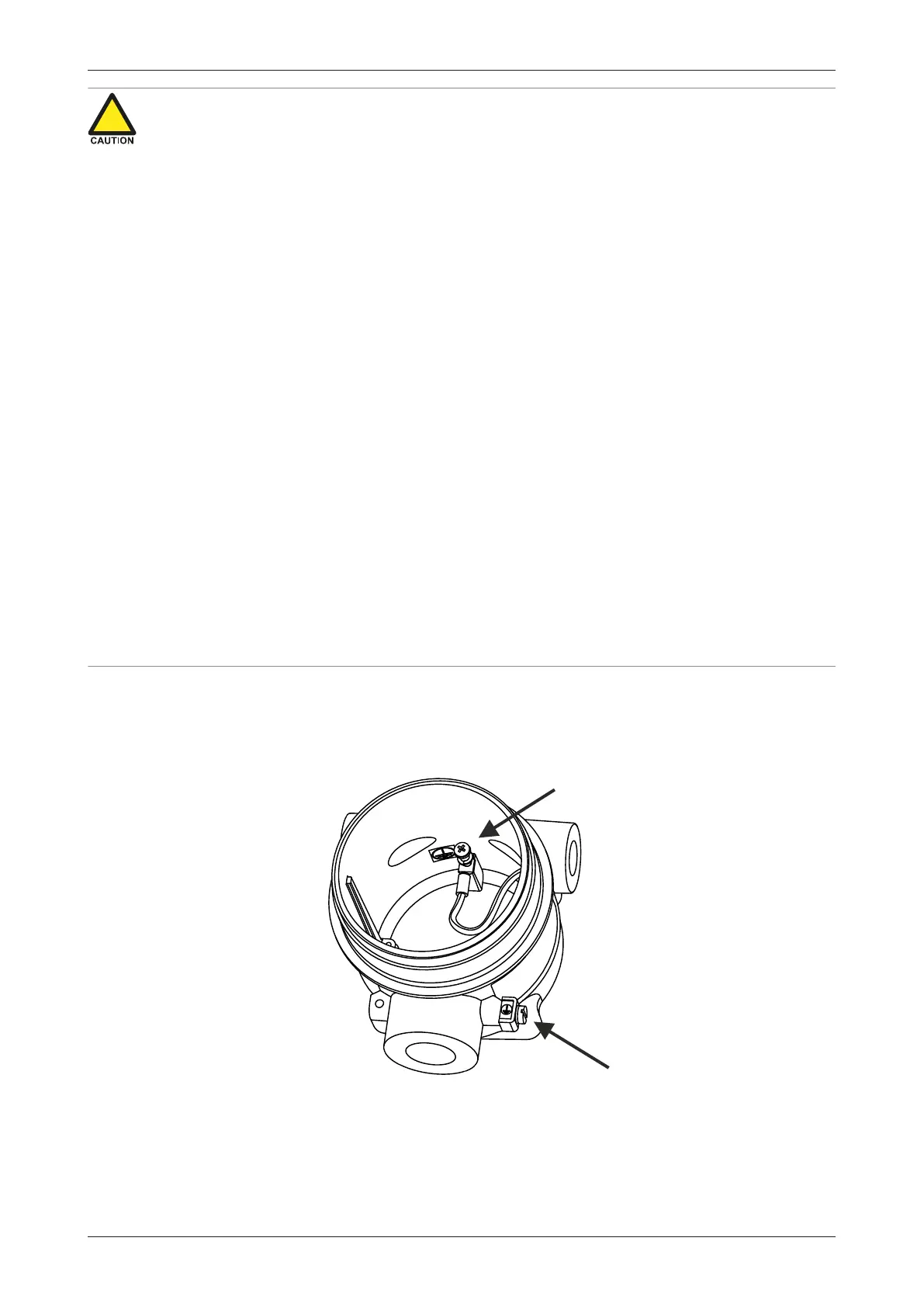
6.4.2 GROUNDING OF THE ENCLOSURE
Make sure to apply proper in- and external grounding to the PE terminals, as shown below. When
the internal ground terminal is used, apply a suitable cable lug.
Wire requirements: stranded conductor 4 mm
2
, single conductor 6 mm
2
.
Fig.24: Grounding of enclosure