E018-P
Page 48 FW_E018-P_M_v0302-02_EN
Active signals 8.2 V and 24 V
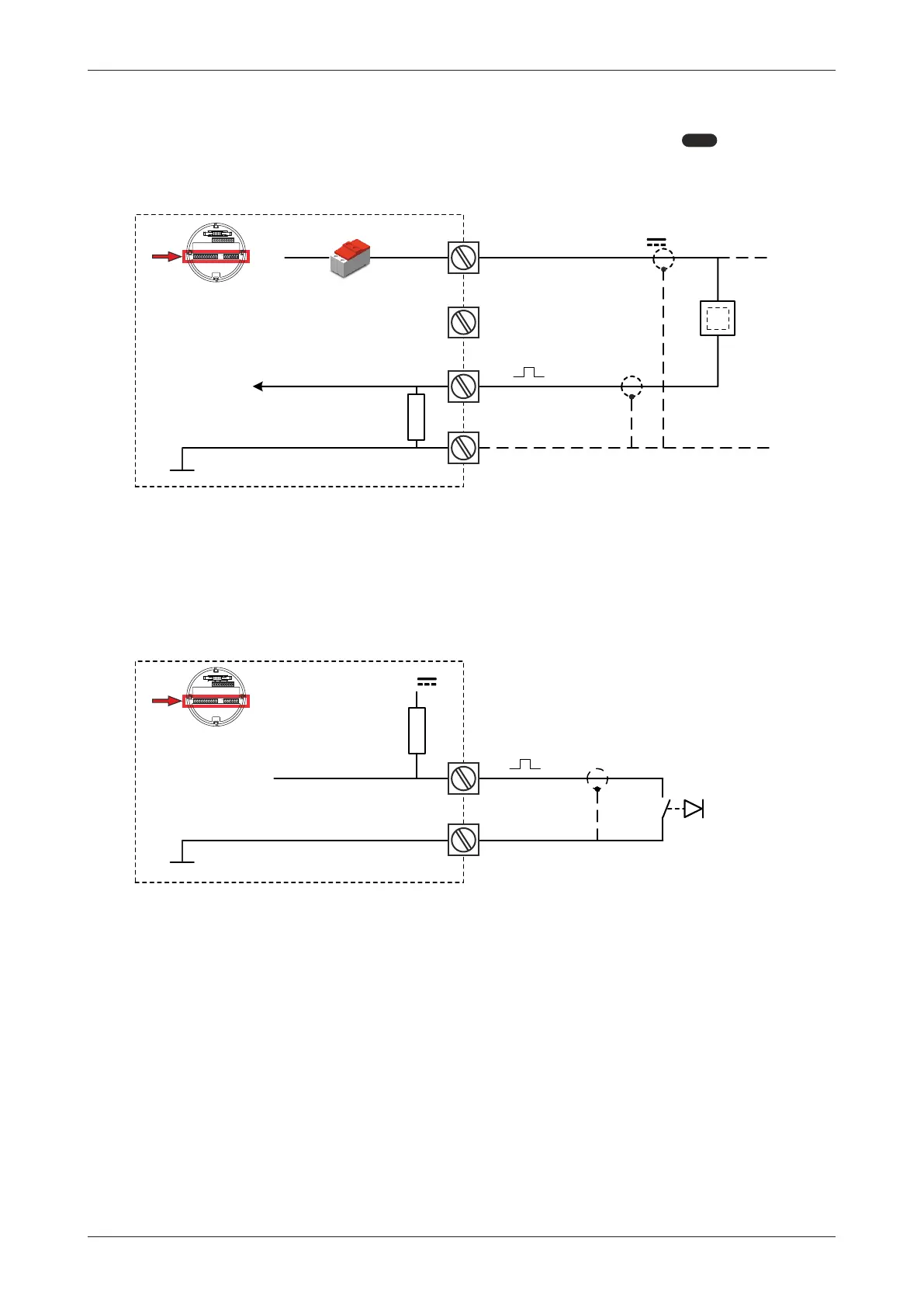
The unit is suitable for flowmeters with an Active signal. The detection levels are about 50% of the
selected supply voltage; approximately 4 V (ACT_8.1) or 12 V (ACT_24). See
5:
FLOWMETER[»25] for more information.
Active signal selection may be desired in the case of power supply type PD being supplied for
sensor supply.
S1
S2
P3
↓
+
J1-J2
8.2 ; 12V; 24VV
Common system ground
R
┴
act
S3
MEM
Fig.36: Terminals S1-S2 and P3: Active signal inputs 8.2 V and 24 V
6.4.11 TERMINALS E1-E2: EXTERNAL RESET WITH CLEAR-LOCK - TYPE IB
Use this function to reset the total to zero with an external switch (pushbutton). The total resets the
moment a falling edge is detected (the moment the switch closes).
To disable the ”Clear Total”-function of the optical keys, keep this input closed.
Make sure the contact resistance of the switch is less than 0.8 V@2uA = 400 kOhm. A reset pulse
should last for at least 100 ms. The input must be switched with a normally open contact to GND.
R
3V
E1
┴
E2
Common system ground
MEM
Fig.37: Terminals E1-E2: External reset
6.4.12 TERMINALS A1-A2: ISOLATED ANALOG OUTPUT – TYPE AH
The flowrate proportional output (AH) is standard available. This output is an isolated 4-20mA
output with the possibility to power the device via the 4-20mA loop. It is non-polarity sensitive.