E018-P
FW_E018-P_M_v0302-02_EN Page 35
Re-assembling the unit
1. If applicable: check that the battery is correctly
inserted and connected to the supply module (BSM /
RSM). See Section 7.3: Battery replacement
instructions[»50].
2. If applicable: plug the cable connectors with
connected wiring into the RSM.
3. Rotate the MEM to the required position (0°, 90°,
180° or 270°) and position it in front of the housing.
4. If applicable: connect the flat cable and lock it.
5. Plug the cable connectors with connected wiring into
the back of the MEM.
6. Insert the MEM into the housing, making sure the
wiring is not damaged or pinched.
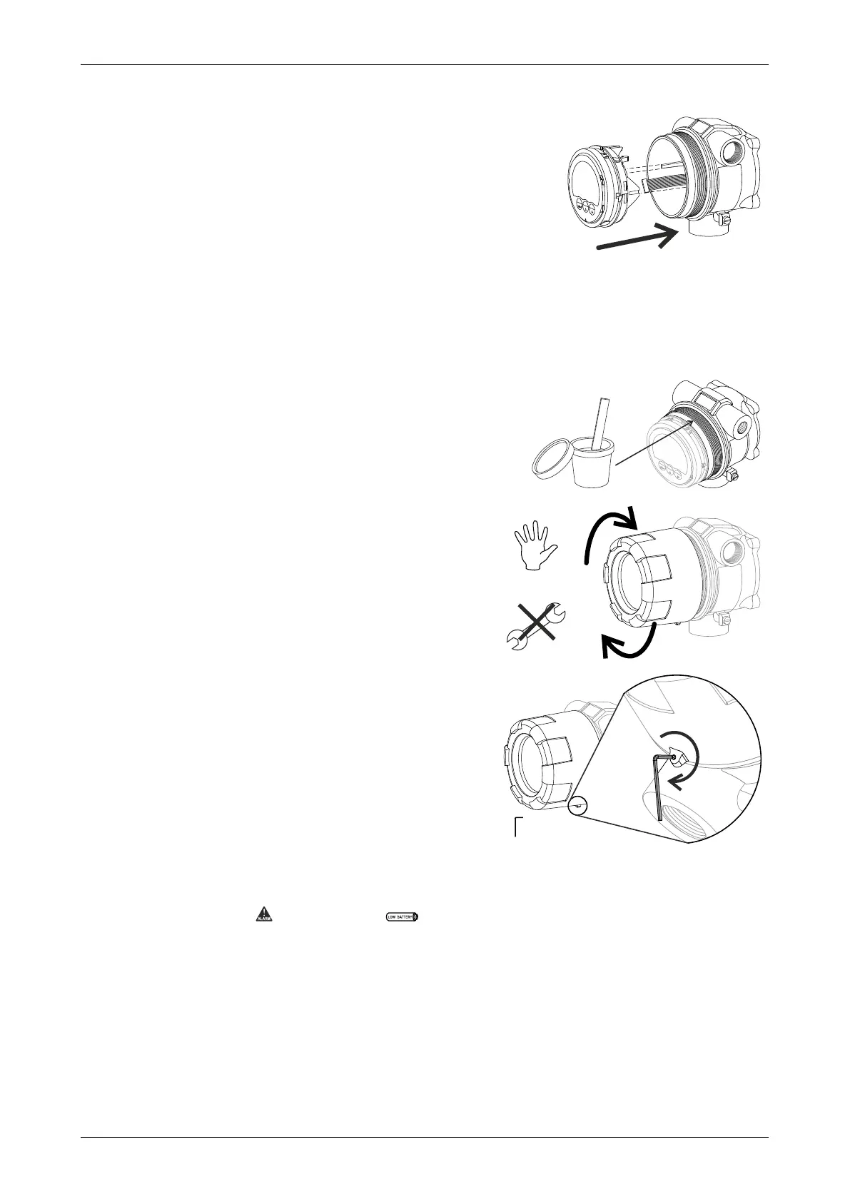
Closing the cover
1. Apply a very thin layer of the specified anti-seize
compound (see Section A: Technical
specification[»52]) on the first two wire threads and
O-ring of the housing.
2. Hold the cover in the correct position for installation.
3. By hand, screw the cover clockwise onto the
housing until the O-ring is tight to meet the required
IP or TYPE protection rating.
4. Lock the cover in place with the fixing screw.
6.2.4 TEST UNIT
After powering up the unit, check the functions of the display to ensure all connections are correct:
● Check that the indicator and the indicator are not lit. See Section 4.5: Operator
alarms[»13].
● Test the optical keys (if applicable), for example by entering SETUP mode and moving around
the menu (see Section 4.2.2: Optical keys[»10]).
● Verify the process accuracy and correct functioning of all inputs and outputs. Consult Section B:
Troubleshooting[»56] in case of any errors.