E018-P
FW_E018-P_M_v0302-02_EN Page 31
6 INSTALLATION
● Mounting, electrical installation, start-up and maintenance of this instrument may only be
carried out by trained personnel authorized by the operator of the facility. Personnel must read
and understand this Operating Manual before carrying out its instructions.
● The E018-P may only be operated by personnel who are authorized and trained by the operator
of the facility. All instructions in this manual are to be observed.
● Ensure that the measuring system is correctly wired up according to the wiring diagrams.
Protection against accidental contact is no longer assured when the housing cover is removed
or the panel cabinet has been opened (danger from electrical shock). The housing may only be
opened by trained personnel.
● Take careful notice of the Section 2: Safety[»5] at the front of this manual.
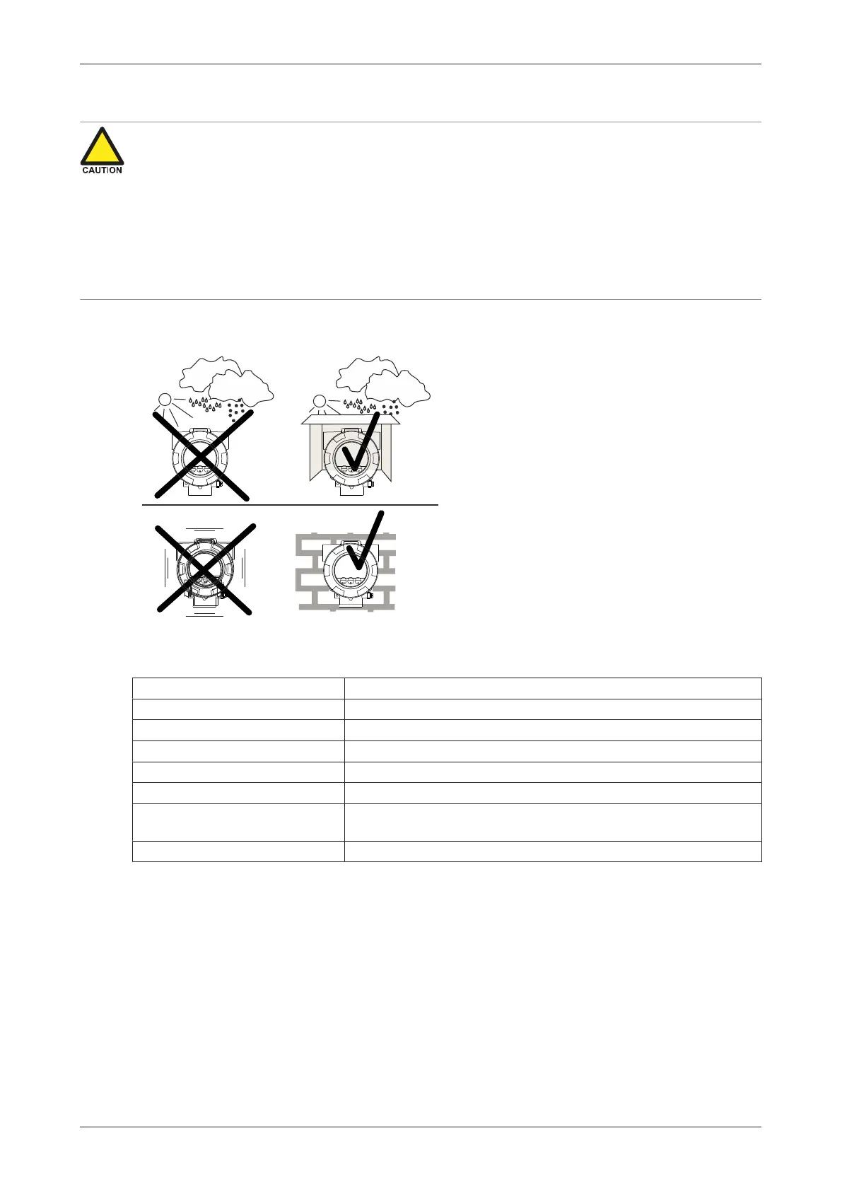
6.1 INSTALLATION / ENVIRONMENTAL CONDITIONS
Take the relevant IP classification of the
enclosure into account (see identification plate).
Even an enclosure rated for IP67 / TYPE 4(X)
should NEVER be exposed to strongly varying
(weather) conditions.
When used in very cold environment or varying
climatic conditions, inside the instrument case,
take the necessary precautions against moisture.
Mount the E018-P onto a solid structure to avoid
vibrations.
For use in Safe Areas, also known as Ordinary Locations, and Hazardous Locations, the following
conditions apply:
Relative humidity: < 90% RH
IP and Type rating: IP66, IP67 and Type 4X, Type 7, Type 9
Supply voltage fluctuation: +/- 10% unless stated otherwise
Means of protection: Class I
Over-voltage category: II
Pollution degree: 2 (internal environment), 3 (external environment)
Ambient temperature: Aluminum enclosure: -40 °C to +70 °C (-40 °F to +158 °F)
Stainless steel enclosure: -40 °C to +67 °C (-40 °F to +153 °F)
Altitude: up to 2000 meters (6600 feet)