E018-P
FW_E018-P_M_v0302-02_EN Page 13
● If a password is assigned in
1.4: TOTAL > CLEAR PASSWORD[»21], the operator is prompted to
enter the password before Total can be reset.
● Type IB – External reset allows to clear Total via an external pushbutton. This clear action
operates in parallel with the clear total procedure of the control panel but does not require any
extra confirmation or password. When the external pushbutton connection is permanently
closed, Total continues to count but cannot be reset to zero via the control panel anymore.
4.4 DISPLAYED INFORMATION
4.4.1 FLOWRATE
The main screen shows the primary process values of the unit. By default, Total is shown on the
upper line of the display and Flowrate on the bottom line:
● The flowrate calculation is based on the configuration settings for
2: FLOWRATE[»21], and
Flowrate is shown with the configured number of decimals.
● The configured unit and time unit are indicated on the bottom line of the display. If there isn’t
enough room available, the display will toggle between unit and time unit.
● “-------“ indicates that the flowrate value is too large to be displayed.
● The arrows and indicate the trend (increase or decrease) of the flowrate.
● The flowrate is calculated and processed 8 times per second. To obtain a readable value, the
flowrate shown on the display is updated once every second.
Speedometer
A speedometer view of the actual flowrate can be shown along the top edge of the display. It
contains 20 segments from 0 to 100%. The speedometer is configured in
4: DISPLAY[»23].
4.4.2 TOTAL AND ACCUMULATED TOTAL
Measured flow is added to the counters for Total and Accumulated total continuously. When
displayed, Total is shown on the upper line and Accumulated total on the lower line:
● Total will count up to 9.999.999 before rolling over to ‘0’ and can be reset to zero by the operator
– see Section 4.3.3: Clearing Total[»12].
● Accumulated total will count up to 99.999.999.999 before rolling over to ‘0’ and cannot be reset.
● Measurement unit and number of decimals of the counters are set in
1: TOTAL[»21].
4.5 OPERATOR ALARMS
4.5.1 FLOWRATE ALARM INDICATION
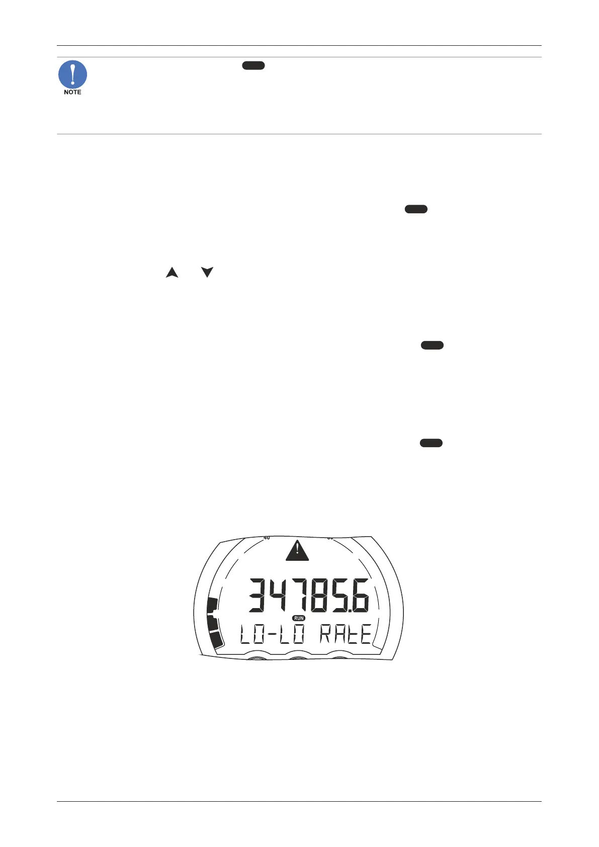
When the flowrate monitoring function is enabled and high or low flow is detected, the alarm-flag is
shown on the display and the information on the bottom line will toggle between the normal
information and an indication of the flowrate alarm.
RATE
GAL
TOTAL
ALARM
0 001
10
30
20
80
90
70
Fig.7: Example of LO-LO flowrate alarm