E018-P
FW_E018-P_M_v0302-02_EN Page 33
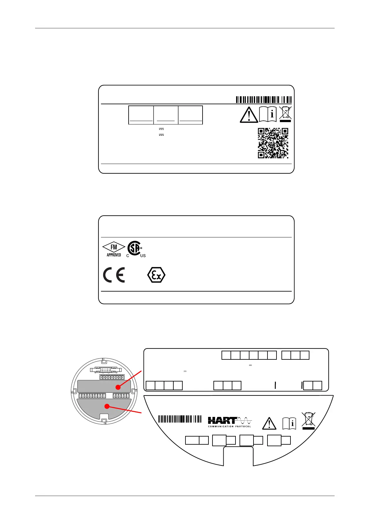
6.2.2 IDENTIFICATION
Your product is supplied with two external and several internal labels.
Configuration label
All E-Series enclosures are supplied with a weatherproof configuration label placed on the outside of
the unit. Information on this label includes the configuration options chosen for your product.
E018 Flow monitor / Totalizer
E018-P-AH-CR-HAA-IB-OR-PD-XD-ZB
S/N: 0000000
THREAD
SIZES:
LEFT
CENTER
RIGHT
3/4" NPT
1" NPT
3/4" NPT
Supply P1-P2: 9-27V
Supply P5-P6: 24-27V
ATEX, IECEx, CSA GROUP A: SEAL IMMEDIATELY AT ENCLOSURE
WALL. OTHERWISE, SEAL ALL CONDUITS WITHIN 18 INCHES.
ATEX, IECEx, CSA GROUPE A: SCELLEZ LES ENTRÉES AU DROIT
DE L'ENVELOPPE. SINON, SCELLEZ TOUTES LES ENTRÉES DE
CONDUITS À 18 INCHES MAX.
, max. 3 W
, max. 4 W
(use only if P5-P6 not present)
Fluidwell BV, Voltaweg 23, Veghel, The Netherlands.
Mfg.Date: -052023
Additional information
FW-E-THRD-AG-V2.4.1
Fig.18: Configuration label
Certification label
Also located on the outside, the Certification Label shows important certification information of your
product.
E-series
Flow Monitor / Totalizer
Tamb: -40°C...+70°C
-40°F...+158°F
IP66/IP67, Type 4X
Explosionproof: Class I, Division 1, Groups A, B, C, D
Dust-Ignitionproof: Class II/III, Division 1, Groups E, F, G
Class I, Zone 1, AEx d IIC T6 Gb
Zone 21, AEx tb IIIC T85°C Db
FM20US0082X - CSA.15.70010647
WARNING - DO NOT OPEN WHEN AN EXPLOSIVE ATMOSPHERE IS PRESENT
FW-E-T6LFT-AG-V1.4.1
AVERTISSEMENT - NE PAS OUVRIR SI UNE ATMOSPHÈRE EXPLOSIVE EST PRÉSENTE
II 2 G Ex db IIC T6 Gb
II 2 D Ex tb IIIC T85°C Db
DEKRA 14ATEX0006 X - IECEx DEK 14.0001X
0344
Fig.19: Certification label
Installation labels
At the inside, several labels can be found. These labels indicate serial number of the electronics,
product configuration and connectors, and more. The MEM is supplied with two labels:
S1 S2 S3 P3 E1 E2 A1 A2
P1 P2 R1 R2 R3 R4 R5 R6 R7
E3
P3: Power out: selection J1/J2
S3: Sensor ref.: 1.2/3V
S2: Sensor signal, type Pulse
S1: Common
E3: Not Connected
E2: Remote input 1 (Reset)
E1: Common
P1: Common
P2: Supply: 9-27V
3W,105mA@24V
R1: Common
R2: Dig. Out 1
R3: Common
R4: Dig. Out 2
R5: Common
R6: Dig. Out 3
R7: Dig. Out 4
A1/A2: Ana. outp. 4-20mA
(HART comm.)
FW-E-MEM-IL-V2.5.1-2/2
SERVICE
E018 Flow monitor / Totalizer
E018-P-AH-CR-HAA-IB-OR-PD-XD-ZB
S/N: 0000000
J1
J2
Power
out P3
J1
J2
24V=
max.
75mA
X
à
12V=
max.
30mA
ß
à
8.2V=
max.
20mA
ß
ß
0
0
0
0
-
0
0
0
0
F
W
-
E
-
M
E
M
-
I
L
-
V
2
.
5
.
1
-
1
/
2
M
a
d
e
i
n
t
h
e
N
e
t
h
e
r
l
a
n
d
s
-
w
w
w
.
f
l
u
i
d
w
e
l
l
.
c
o
m
Fig.20: Example MEM labeling