E018-P
Page 34 FW_E018-P_M_v0302-02_EN
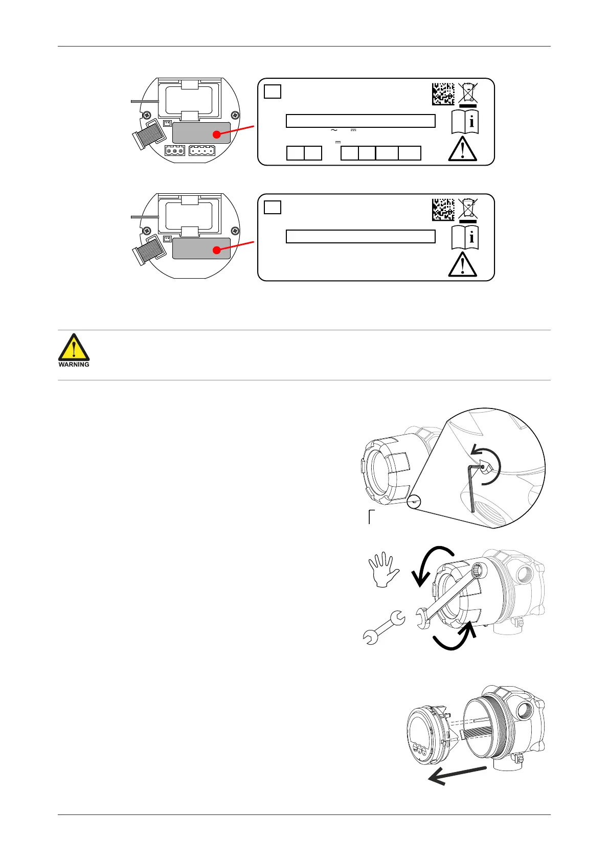
Depending on product type, the optional Supply Module (RSM or BSM) is also labeled:
RSM - Relay Supply Module
Only use factory supplied battery, spare part nr. SPB02.
Fire, explosion or severe burns may result if mistreated.
Do not recharge, crush, disassemble, incinerate, heat
above 100°C (121°F) or expose contents to water.
XX000000-X00-0000-0000
Batt.
conn.
Fluidwell
Spare part nr. SES02
www.fluidwell.com
P5
P6 R8 R9 R10
R11
R8-R11: Max. 250V / 30V , 1A resistive / 0.5A inductive loads
P5: GND
P6: SUPPLY: 24-27V , 4W, 155mA@24V
R8: COM 6
R9: NO 6
R10: COM 5
R11: NO 5
FW-E-RSM-IRSL-V1.3
Fig.21: Example RSM labeling (Type OR or Type PB-OR)
BSM - Battery Supply Module
Only use factory supplied battery, spare part nr. SPB02.
Fire, explosion or severe burns may result if mistreated.
Do not recharge, crush, disassemble, incinerate, heat
above 100°C (121°F) or expose contents to water.
XX000000-X00-0000-0000
Batt.
conn.
Fluidwell
Spare part nr. SES02
www.fluidwell.com
FW-E-BSM-IBSL-V1.3
Fig.22: Example BSM labeling (Type PB)
6.2.3 OPENING, ASSEMBLING AND CLOSING THE UNIT
Explosion risk: never open the housing when explosive atmosphere is present.
Safety risk: do not open an installed enclosure when circuits are alive.
Pollution risk: prevent any contamination or dirt to enter the enclosure or mounting threads.
Opening the cover
1. Before opening the enclosure, make sure that the
immediate surroundings are clean and free of dirt to
prevent any pollution or contamination entering the
enclosure or mounting threads.
2. Loosen the fixing screw.
3. By hand (or gently with a wrench if tight), turn the
cover counter-clockwise until it is free of the
housing. Make sure the MEM inside doesn’t fall out
or gets damaged. Remove the cover carefully.
4. Store the cover in a safe location. Make sure the
mounting thread and glass screen are protected and
the fixing screw is not lost.
Removing the MEM
1. Carefully pull the MEM out of the housing until the
connectors and wiring become available.
2. Disconnect all cable connectors from the MEM.
3. If applicable: unlock and disconnect the flat cable.
4. Store the MEM in a clean, safe location so LCD and
keyboard are protected.
5. Protect the housing and connectors against ingress
of moist or contamination.