E018-P
Page 42 FW_E018-P_M_v0302-02_EN
Type PD: Sensor supply: 8.2 VDC – 12 VDC or 24 VDC (Vin P2 minus 1 V)
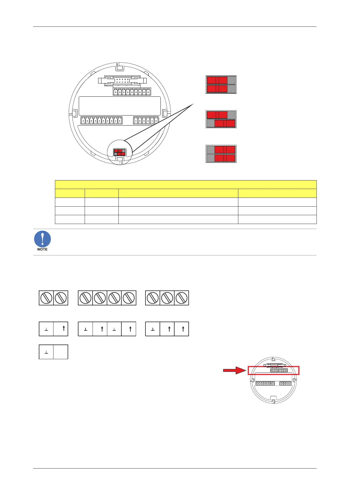
This option provides a supply derived from the input supply. Adjust the P3 output voltage using
switches J1 and J2 on the bottom rear of the MEM (Main Electronics Module) - see following figure.
V input - 1V DC
8.2VDC
12VDC
J1
J2
J1
J2
J1
J2
on off
Fig.25: Voltage selector switch (terminal connector P3)
Power supply 10 – 30 V DC (OFF = right position)
J1 J2 External sensor supply voltage Required supply voltage
ON ON 8.2 V DC (max. output 20 mA) 9 – 27 V DC
ON OFF 12 V DC (max. output 30 mA) 13 – 27 V DC
OFF OFF Supply voltage - 1 V DC (max output 75 mA) Up to 27 V DC
Power overload
The sensor supply is protected against a power overload but an overload may affect the functionality
of the unit (i.e. shutdown).
6.4.5 TERMINAL CONNECTORS – MEM
The following terminal connectors are available for the Main Electronics Modus (MEM).
P2
POWER
REQUIREMENTS
P1
PX: 9 - 27V DC
PD: 9 - 27V DC
R1 R2
D1
R3
+
+
OT: passive transistor output
+
MEM
PB: battery powered
(PX: is standard available: if supply PX/PD
is connected, the battery supply will be
switched off automatically.
R4
+
PULSE OUTPUT/ ALARM S
D2
R5 R6
D3
R7
OT: passive transistor output
+ +
PULSE OUTPUT/ ALARM S
D4
Fig.26: Terminal connectors MEM – upper row