E018-P
FW_E018-P_M_v0302-02_EN Page 43
E1 E2 E3
IB: Reset total/Clear-lock
+
P3S2
S3
SENSOR INPUT
S1
P: reed switch / NPN
P: coil
P: namur
P: PNP
P: active signal
+
-
+
+
3V
+
3V
+
8.2 / 12
/ 24V
-
+
3V
+
8.2 / 12
/ 24V
+
8.2 / 12
/ 24V
+
8.2 / 12
/ 24V
+
8.2 / 12
/ 24V
SENSOR
SUPPLY
LOOP POWERED ANALOG OUTPUT
HART COMMUNICATION
A1 A2
AH: Isolated 4 - 20mA
I
-/+
I
-/+
RESET INPUT
MEM
Note: The sensor supply (P3)
is only available with PD.
CR HART Communication:
I
-/+
I
-/+
Note: Non-polarity
sensitive.
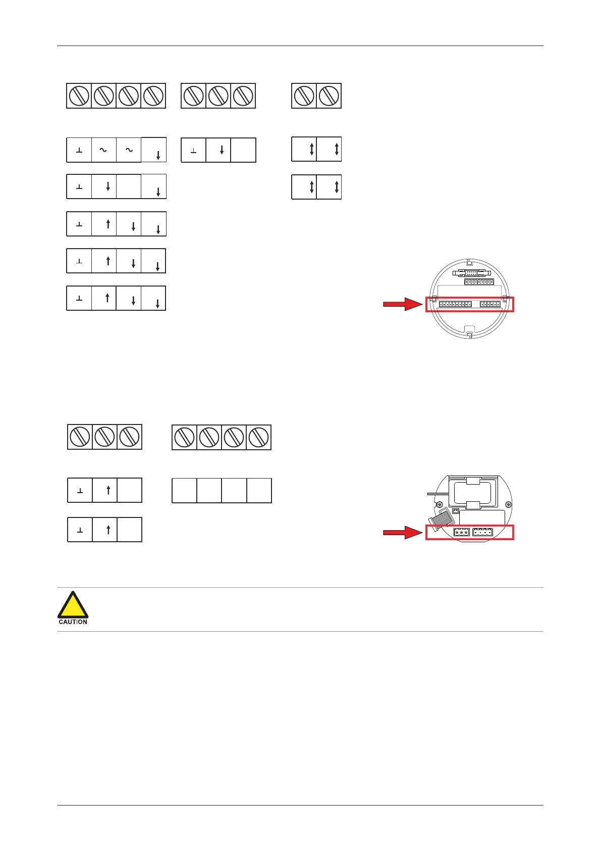
Fig.27: Terminal connectors MEM - lower row
6.4.6 TERMINAL CONNECTORS – RSM
The following terminal connections are available for Relay Supply Module (RSM; option OR).
P5 P6
POWER
REQUIREMENTS
P7
PD: 9 - 27V DC*
+
PX: 9 - 27V DC
+
R8 R9
OR: Relay output*
COM5 NO5
R10 R11
*Type OR requires 24-27V DC and power supply via P5-P6
instead of P1-P2
D6
PULSE OUTPUT/ ALARM S
D5
COM6 NO6
RSM
Fig.28: Terminal connectors RSM
6.4.7 TERMINALS P1-P2 OR P5-P6: POWER SUPPLY – TYPE PD/PX
Power connection differs with or without Type OR
● Without Type OR, power should be connected to MEM terminals P1 and P2.
● With Type OR, power should be connected to RSM terminals P5 and P6.
Connect an external 9-27 VDC power supply to these terminals.
When power is applied to these terminals, discharge of the (optional) internal battery will be
disabled. See also Section 6.4.3: Electrical ratings[»41].
6.4.8 TERMINALS P3: SENSOR SUPPLY - TYPE PD
This terminal may be used for sensor supply. See Section 6.4.4: Voltage selection sensor supply[»41]
for relevant information.
Power requirements for sensor supply P3:
● 8.2 V sensor supply requires 9-27 V
● 12 V sensor supply requires 13-27 V
● 24 V = V-input – 1V (max 27 V)