E018-P
FW_E018-P_M_v0302-02_EN Page 37
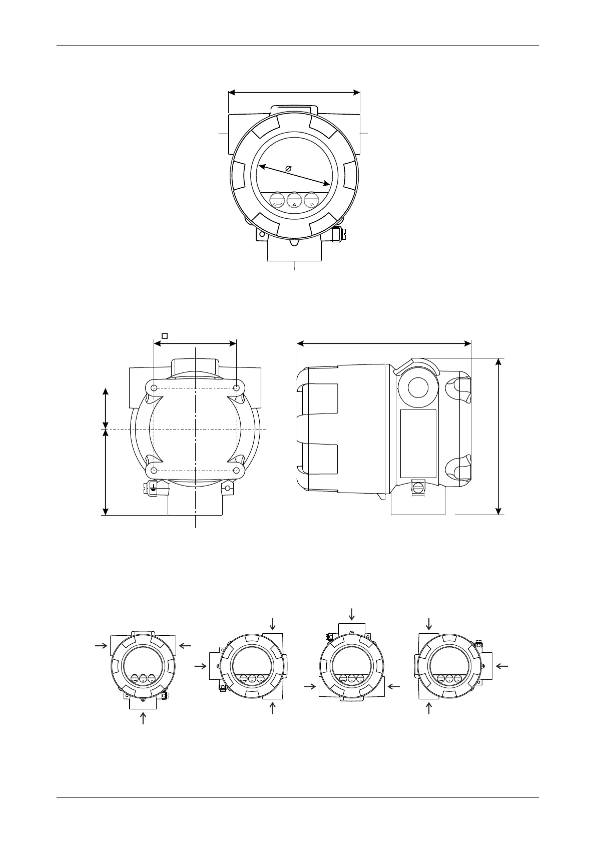
6.3.2 MECHANICAL DIMENSIONS
Right connection
M20x1.5
M25x1.5
½” NPT
¾” NPT
M20x1.5
M25x1.5
½” NPT
¾” NPT
1” NPT
Bottom connection
133mm / 5.24”
148mm / 5.83”
70mm / 2.76”
73mm / 2.87” 35mm / 1.38”
112mm / 4.41”
Left connection
M20x1.5
M25x1.5
½” NPT
¾” NPT
65
Fig.23: Mechanical dimensions of the E-Series enclosure
6.3.3 MOUNTING THE UNIT
The Main Electronics Module (MEM) can be placed into the body in 4 directions (0° – 90° – 180° –
270°). This allows the unit to be mounted in any direction while still allowing the MEM to be installed
in a ‘readable’ position.
By rotating the unit, the process and conduit openings can be placed in the required direction.
Note that the thread sizes of the openings indicated by “left – right – center” correspond with the
information on the configuration label attached to the outside of the product.