E018-P
FW_E018-P_M_v0302-02_EN Page 51
7.3.1 SUPPLY BATTERY REPLACEMENT
Check new battery
Before exchanging the supply battery, make sure the new battery is undamaged, in good condition
and suitable for use in the unit. Check the marking as shown below (Type: StdLiBAT021 – re-
ordering nr. SPB02). Only use batteries that are approved by the manufacturer.
Primary Lithium Battery - Only replace with Fluidwell recommended battery pack!
Pile primaire au lithium - Remplacer uniquement par une pile recommandé par Fluidwell!
WARNINGS:
Consult the manual for replacement instructions.
Fire, explosion or severe burns may result if
mistreated. Do not recharge, crush, disassemble,
incinerate, heat above 100°C (212°F) or expose
contents to water.
AVERTISSEMENTS :
Consulter le manuel pour connaître les consignes
de remplacement.
Une mauvaise utilisation peut entraîner un incendie,
une explosion ou de graves blessures.
Ne pas recharger, écraser, démonter, incinérer,
chauffer à plus de 100°C (212°F) ou exposer à l'eau.
Uo = 3.6V / Size AA x 3
SPB02-1.1
SPB02
Re-order no. :
<DATE YYYY-MM>
Fluidwell BV
www.fluidwell.com
Fig.40: Marking supply battery: StdLiBAT021 (SPB02)
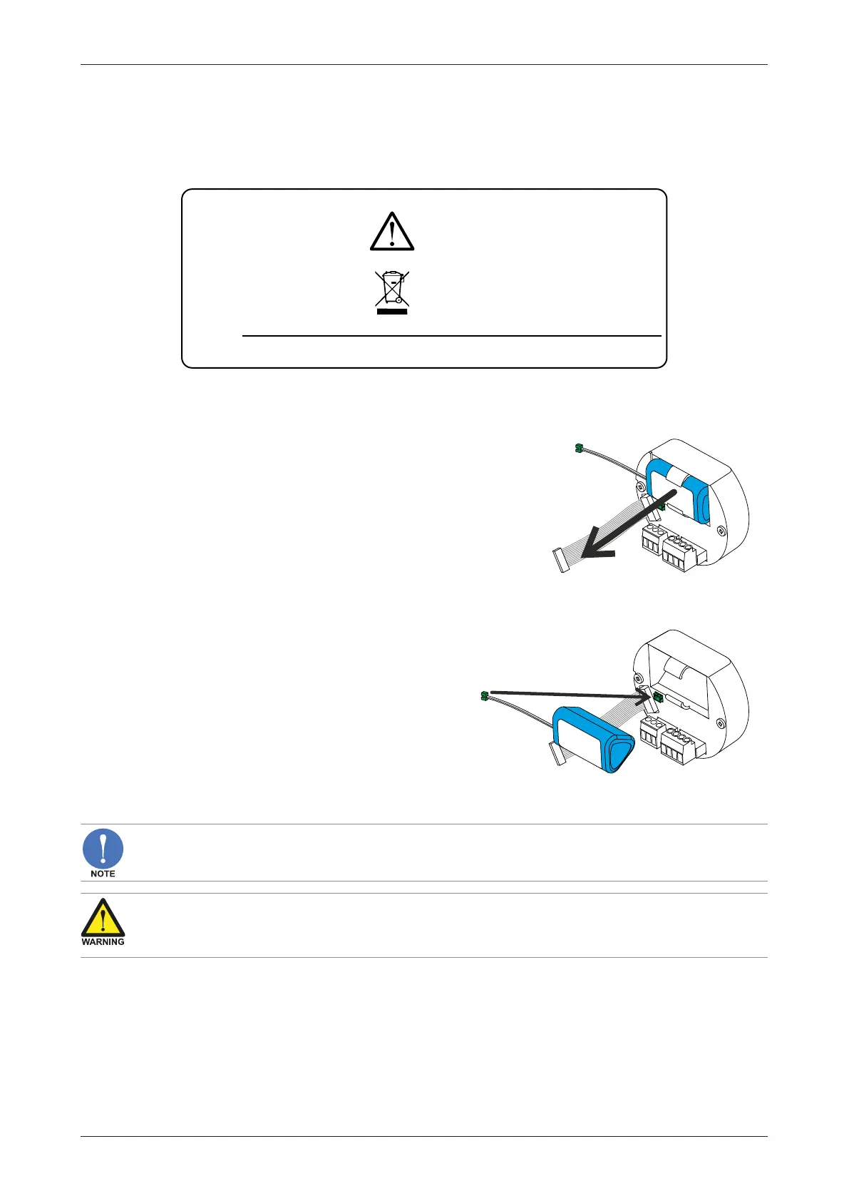
Remove the old battery as follows:
1. Disconnect the battery connector cable from
the supply module.
2. Carefully remove the battery from the holder.
3. Store the old battery in a small plastic bag (e.g.
the bag the new battery came in) or install an
insulation tape over the battery connector to
prevent a short circuit.
4. Dispose of the battery according to the local
environment regulations
Install the new battery as follows:
1. Carefully press the battery fully into the battery
holder.
2. Carefully click the battery connector cable into
its connection in the supply module.
7.4 REPLACE SILICA GEL SACHET
A silica gel sachet is not supplied with the product but may have been placed during or after
installation to prevent condensation.
Incompatibility risk
Do not use silica gel in environments where hydrogen fluoride, strong acids and/or strong bases are
to be expected
1. Follow the instructions shown in Section 6.2.3: Opening, assembling and closing the unit[»34], to
gain access to the inside of the housing.
2. Remove old silica-gel sachet from housing and replace with a new dry sachet.
3. Dispose of waste in accordance with (inter)national, manufacturer and plant owner standards
and regulations.