E018-P
Page 32 FW_E018-P_M_v0302-02_EN
6.2 HANDLING THE E-SERIES ENCLOSURE
6.2.1 MAIN PARTS
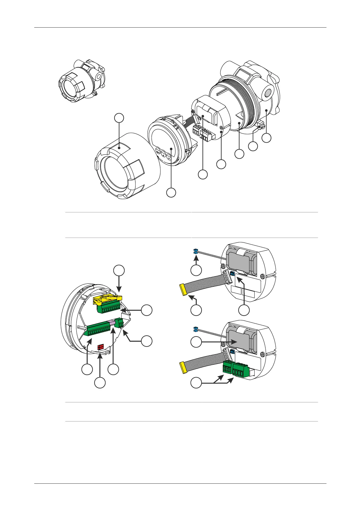
Fig.16: Exploded view
1. Cover 5. Body
2. Main Electronics Module (MEM) 6. Grounding terminal
3. Battery 7. Label
4. Supply Module (RSM or BSM)
Fig.17: Main Electronic Module and two types of Supply Module (BSM, RSM)
1. Flatcable connector 4. Sensor supply voltage selection switches
2. Terminal connectors 5. Battery connector
3. PC configuration / communication connector 6. Battery