E018-P
Page 10 FW_E018-P_M_v0302-02_EN
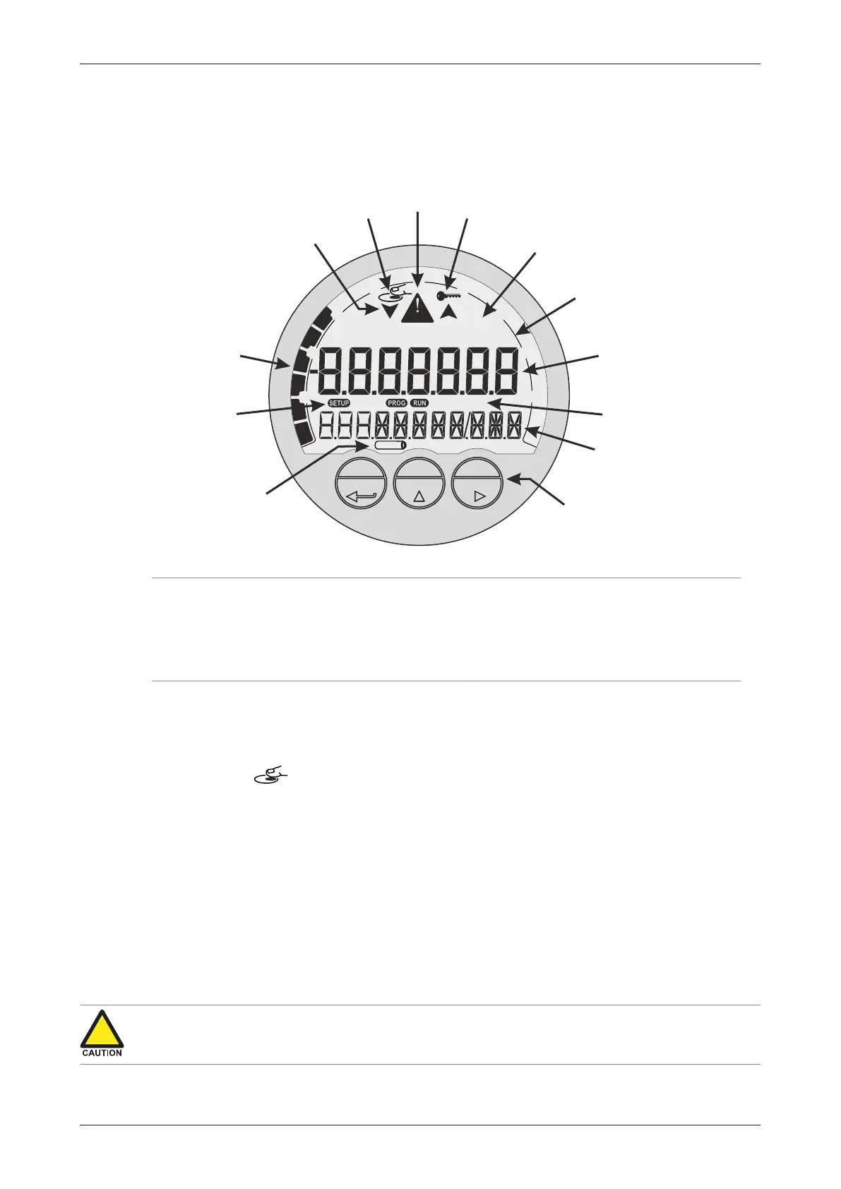
The display contains one line with large digits at the top and one line with small digits at the bottom.
The top line is mainly used to display key process information, while the bottom line usually displays
less important information or system messages.
Both lines are surrounded by various symbols to indicate operating mode, function, status and
measurement unit. The following image shows this in more detail:
PROG SELECT CLEAR
0
ACC.TOTAL
RATE
bbl lb
3
ft
3
m
USIGALkg
ton
TOTAL
standard
0x10 0
001
LOW BATTERY
10
30
20
40 60
80
90
70
ALARM
12
2
3
4
5
6
9
11
13
10
8
7
1
Fig.4: Display layout and important symbols
1. Optical keys: PROG, SELECT, CLEAR 8. Alarm indication symbol
2. Small digits – bottom line 9. Optical keys activation indicator
3. Current function – bottom line 10. Trend indication arrows (increase / decrease)
4. Large digits – top line 11. Speedometer
5. Measuring unit – top line 12. Mode indicators: RUN, SETUP, PROG
6. Current function – top line 13. Low battery indicator
7. Key lock symbol (for optical keys)
4.2.2 OPTICAL KEYS
The optical keys are used to control the unit ‘through the glass’ without the need to open the
enclosure. To activate an optical key, position a finger (clean and without gloves) in front of the glass
above the indicated area for PROG, SELECT or CLEAR. Correct key operation will result in the
activation indicator to show on the display. After the indicator is shown, the finger can be
removed and the selected key ‘is pushed’.
The optical keys only work reliably when the glass is clean. Try to avoid actually touching the glass
as this could leave smudges. Clean the glass regularly with a lint free cloth dampened with (soapy)
water.
False activation or bad responses of the optical keys can also be caused by:
● Dirt, grease or dust on the glass.
● Shiny surfaces positioned up to 100 mm (4 inches) in front of the display.
Key lock function
To prevent any erroneous operations due to false optical key activation, a key lock function is
implemented. When the function is enabled (default), the optical keys are automatically locked if no
optical key is activated for 30 seconds.
● False optical key activations can cause erroneous operation and reduce the battery lifetime
significantly. Therefore, it is advised to keep the key lock function enabled.
● When battery powered, the backlight will only come on after the unlock sequence is finished.