THEORY
OF
OPERATION
3-66.
STATUS
AND CONTROL
Tri-stale
buffers
Ull and U40
read
the three
hardware
fault
detector
status
signals,
UNLVL,
UNLOKL and
RPTRPL, the five
option status
signals
HSOPTL,
MSREFL,
lEINL, LRFML, and
ROPTL, and
the
status of the REF
INT/ EXT
switch.
Control and
buffer
enable signals are
latched by U17.
3-67. REAR
SECTION, A3
The
rear panel section
consists of
a fuse/ filter/
line-voltage selector
switch A3FL1, a
transformer A3T1, a
Power Supply PCA
A3A1,
and a fan,
A3BL The
line-selector
switch
accommodates four line
voltages, 100/120/220/240
volts, selected by
the
orientation of a
pullout
PCB.
The
transformer
A3T1, with its two
primary
windings,
accepts
these four
voltages and
produces
the necessary five secondary
voltages. The
power
supply PCA A3A1
rectifies,
filters,
and regulates these
secondary
voltages to
produce
the dc voltages
required by
the
Generator. The dc fan
A3BI is connected to
the
unregulated
+5V supply.
NOTE
The power
supply
for
Option
-130
High-Stability Reference is
separate. It has
an
automatic
change over switch
for
different
input line voltages.
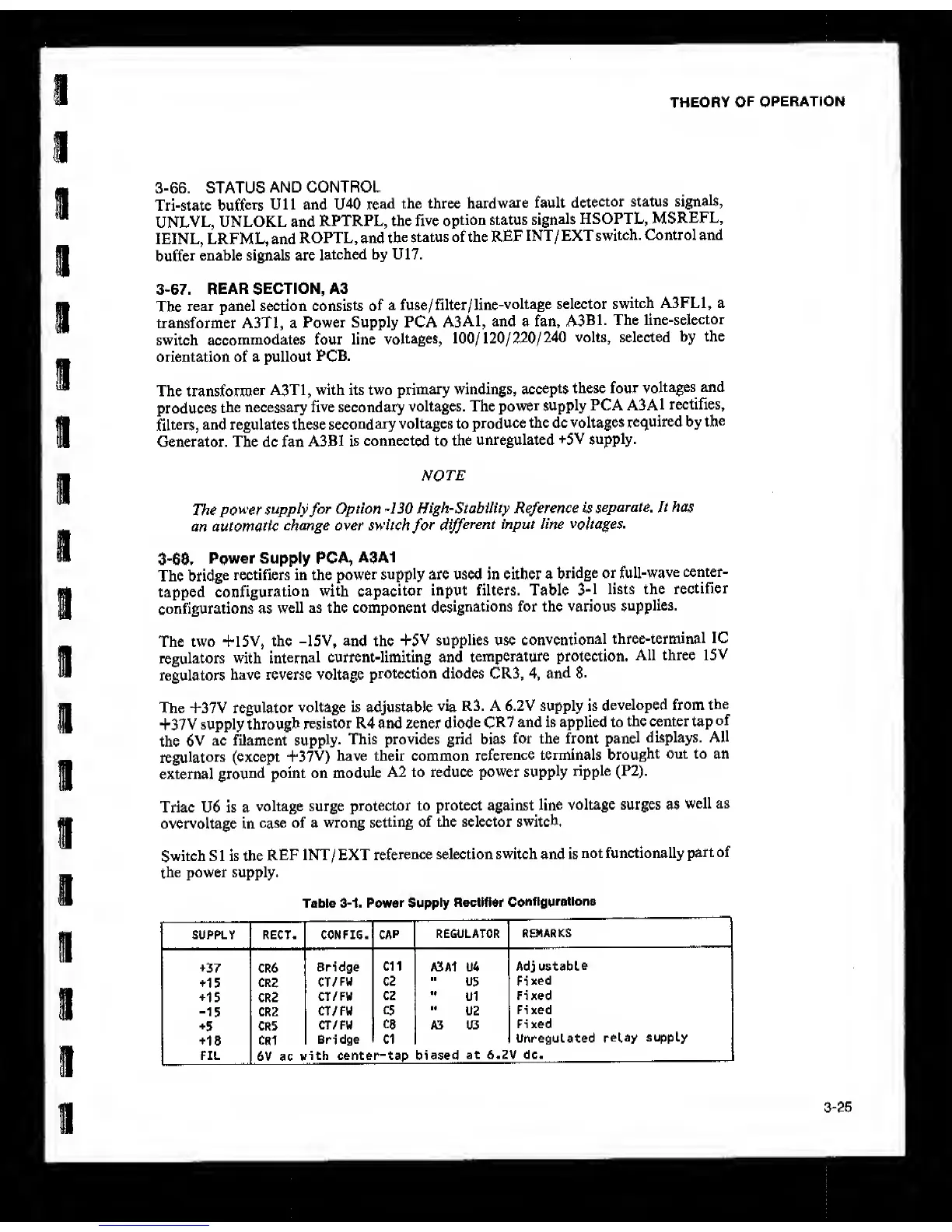
3-68.
Power Supply PCA,
A3A1
The
bridge
rectifiers in the
power
supply are used in either a
bridge or
full-wave
center-
tapped
configuration
with
capacitor
input filters. Table
3-1
lists the
rectifier
configurations as
well as the component
designations for the various
supplies.
The two
+15V, the -15V, and the
+5V supplies use
conventional
three-terminal
IC
regulators with
internal
current-limiting and
temperature protection.
All three
15V
regulators
have reverse voltage
protection diodes CR3,
4,
and
8.
The +37V
regulator
voltage is adjustable
via R3. A 6.2V supply is
developed from
the
-|-37
V supply
through
resistor R4 and zener
diode CR7
and is applied to
the center tap
of
the
6V ac filament
supply.
This provides grid bias
for the front
panel
displays.
All
regulators
(except
+37V) have their common
reference
terminals
brought
out to an
external
ground
point on
module
A2 to reduce power
supply
ripple (P2).
Triac U6 is a
voltage surge
protector
to protect against
line
voltage surges as
well as
overvoltage in
case of a wrong
setting
of the selector
switch.
Switch S 1 is the
REF INT/ EXT
reference selection switch and is
not functionally
part of
the power supply.
Table
3-1.
Power
Supply
Rectifier
Configurations
SUPPLY SECT, CONFIG.
CAP
REGULATOR
REMARKS
+37
CR6
Bridge
C11
A3A1 UA
Adj
ustable
+15
CR2
CT/FW
C2
”
U5 Fi
xed
+15
CR2
CT/FW
C2
"
U1
Fixed
-15
CR2
CT/FW
C5
"
U2
Fi xed
+5 CR5
CT/FW
C8
A3 U3
Fi xed
+18 CR1
Bridge Cl
Unregulated
relay
supply
FIL
6V ac
with center-tap biased
at 6.2V dc.
3-25