INSTALLATION AND OPERATION
tm
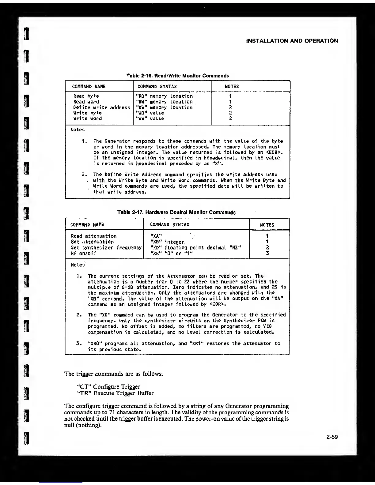
Table
2-16.
Read/Write Monitor Commands
CONMAND NAME COMMAND SYNTAX NOTES
Read byte "RB" memory Location 1
Read word "RW" memory Location 1
befine write address "DW"
memory Location
2
Write byte '•WB'* value 2
Write word "WW" value 2
Notes
1- The
Generator
responds to
these
commands with the
value
of the
byte
or word in the memory location addressed. The memory Location must
be an unsigned integer. The value returned is followed by an <E0R>.
If the memory Location
is
specified
in
hexadecimal, then
the value
is returned
in
hexadecimal
preceded by an "X".
2. The [>efine Write Address command
specifies the
write address used
with the Write Byte and Write Word commands. When the Write Byte and
Write Word commands are used, the specified data will be written to
that write address.
Table
2-17.
Hardware Control Monitor Commands
COMMAND
NAME
COMMAND
SYNTAX
NOTES
Read attenuation *'XA" 1
Set attenuation "XB"
integer.
1
Set synthesizer frequency ••XD» floating point decimal "MZ" 2
RF on/off "XR”
"0"
or
*'1"
3
Notes
1. The current settings of the Attenuator can be read or set. The
attenuation
is
a number
from
0
to 23 where the number specifies the
multiple of 6-dB attenuation. Zero indicates no attenuation,
and 23 is
the maximun attenuation. Only the attenuators are changed
with the
"XB” command. The value of
the attenuation will
be output on the "XA"
command
as
an unsigned
integer
followed
by <E0R>.
2. The "XD" command can
be used to program
the Generator to the specified
frequency-
Only the synthesizer circuits
on
the Synthesizer
PCB is
programmed. No offset is added, no filters are programmed, no VCO
compensation
is
calculated, and
no
level correction is
calculated.
3. ''XRO" programs all attenuation, and "XRV restores the
attenuator
to
its previous state.
The trigger
commands
are
as
follows:
“Cr’ Configure Trigger
“TR” Execute Trigger Buffer
The configure trigger command is followed by a string
of
any Generator programming
commands up to 71 characters in length. The validity of the programming commands is
not checked until the trigger buffer is executed. The power-on value
of
the trigger string is
null (nothing).
2-59