INSTALLATION AND OPERATION
Table
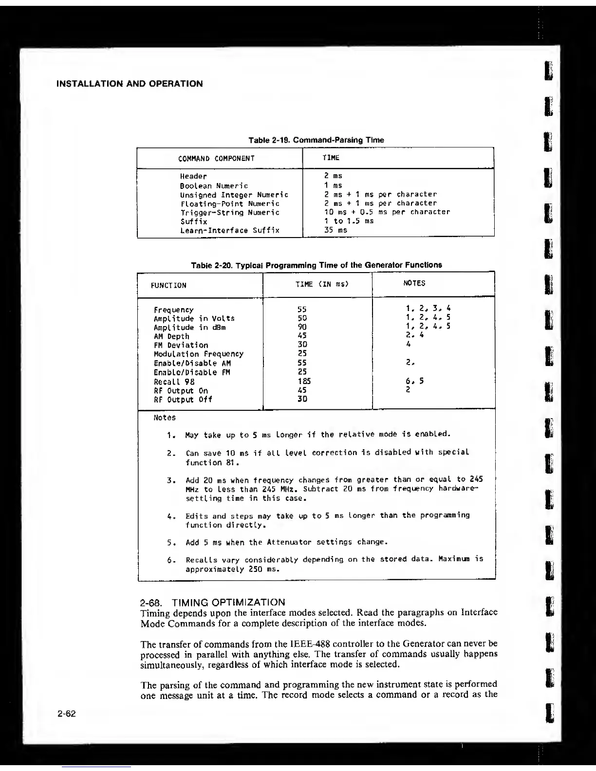
2-19- Command-Pareing Time
COMMAND
COMPONENT
Header
Boolean
Numeric
Unsigned Integer
Numeric
Floating-Point
Numeric
Trigger“String
Numeric
Suffix
Learn-Interf ace
Suffix
2 ms
1 ms
Z ms
+
1 ms per
character
Z ms
+
1 ms per
character
10 ms
+
0-5
ms
per
character
1 to 1 .5
ms
35 ms
Table
2-20.
Typical
Programming Time of
the Generator Functions
FUNCTION
TIME (IN ms)
NOTES
Frequency
55
1, 2.
Amplitude
in
Volts
50
1. 2.
Amplitude
in
dBm 90
U
2.
AM
Depth
45
1
2.
4
FM
Deviation
30
Modulation
Frequency
25
Eneble/DlsebU AM
55
2.
Enable/Pisable PM
25
Recall 98
185
i
6* 5
RF Output On
45
2
RF Output Off
30
Notes
1. May take up to 5
ms Longer if the
relative
mode is
enabled.
2. Can save 10 ms if all Level
correction is
disabled
with special
f uncti on 81
.
3. Add 20 ms when frequency
changes from greater
than
or equal to 245
MHz to Less than 245 MHz.
Subtract 20 ms from
frequency
hardware-
settling time in this case.
4.
Edits and steps may take up to 5
ms Longer than
the
programming
function directly.
5. Add 5 ms when
the
Attenuator settings
change.
6. Recalls
vary
considerably
depending on the stored
data. Maximun is
approximately 250
ms.
2-68.
TIMING
OPTIMIZATION
Timing depends upon
the interface modes selected. Read the
paragraphs on Interface
Mode
Commands for a complete
description
of the interface modes.
The
transfer of commands from
the
IEEE-488 controller to the Generator can
never be
processed
in parallel with anything else.
The transfer of commands usually
happens
simultaneously,
regardless of which
interface mode is selected.
The
parsing
of the
command
and programming the new instrument state
is
performed
one
message
unit at a time. The
record mode selects a command or a
record as
the
2-62