INSTALLATION AND OPERATION
I
I
a.
Press
the [SPCL] and the
[1][0]
keys.
Verify that the selected
address
appears in decimal in the Frequency display
field.
b. If the talk-only
mode
or listen-only mode has been selected,
“to” or “lo”
appears to the left of the address
in the
Frequency display field.
NOTE
The
address
switches are continuously
monitored except
when in remote,
The
TA
LK ONL Y and LISTEN ONL Y
switches
are only read when the
Generator
is
powered on.
2-35. Programming Commands
After the address and mode have
been set, the Generator can be
programmed
by an
IEEE-4S8
controller or from another
Generator. Tables
2-7
and 24
and the
programming
examples following them
provide the basic information
on
how to
program
the Generator.
More details about the
commands
can
be
found in two places.
Commands that are
available from the front
panel
are described
in
the first part of
this section. Those
commands
that are only available
from
the IEEE-488 Interface are
described
in
the
Commands
Descriptions
paragraphs later
in
this section
of
the manual.
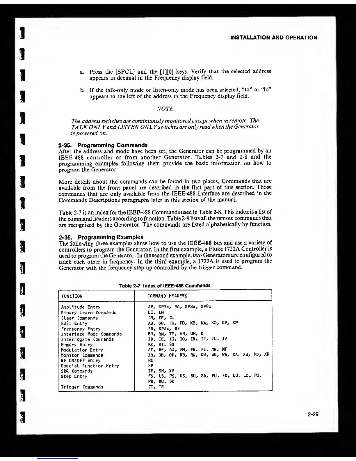
Table
2-7
is
an index for the IEEE-488
Commands used in Table
2-8,
This
index is a list of
the command
headers according to function. Table 24
lists all the remote
commands
that
are recognized by the
Generator. The commands are listed
alphabetically by
function.
2-35. Programming
Examples
The following
three
examples show how to use the
IEEE488
bus and use a
variety of
controllers to
program the Generator. In the first
example,
a Fluke 1722A
Controller is
used to program
the Generator. In the second example,
two Generators are
configured to
track each other
in frequency. In the third example, a
1722A is used to
program
the
Generator with the
frequency step up controlled by
the
trigger command.
Table
2-7.
Index
of
IEEE*488
Commands
FUNCTION
COMMANO HEADERS
Amplitude Entry
AP, SP3x^ RA^ SPSx,
SP9x
Binary Learn
Commands
LI* LM
Clear Commands
CB^ ce* CL
Edit Entry A8,
DB,
FB, PB* KB, KA,
KD, KF, KP
Frequency
Entry
FR, SP2x, RF
Interface
Mode Commands EM, RM,
TM, VM, UM, B
Interrogate Commands
ID,
IE, II,
10,
IR, IT,
lU, IV
Memory Entry RC, ST,
SQ
Modulation Entry
AM, AE, AI, FM, FE,
FI, MR,
MF
Monitor Commands 18,
OB, OD, RB, RW,
DW,
WB, WW, XA,
XB,
XD, XR
RF ON/OFF Entry
RO
Special Function Entry
SP
SRQ Commands
IM, SM, XF
Step Entry FS, LS, PS,
DS,
SU, SD, FU,
FD,
LU, LD, PU,
PD, DU, DD
Trigger
Commands
CT, TR
2-29