INSTALLATION
AND
OPERATION
1
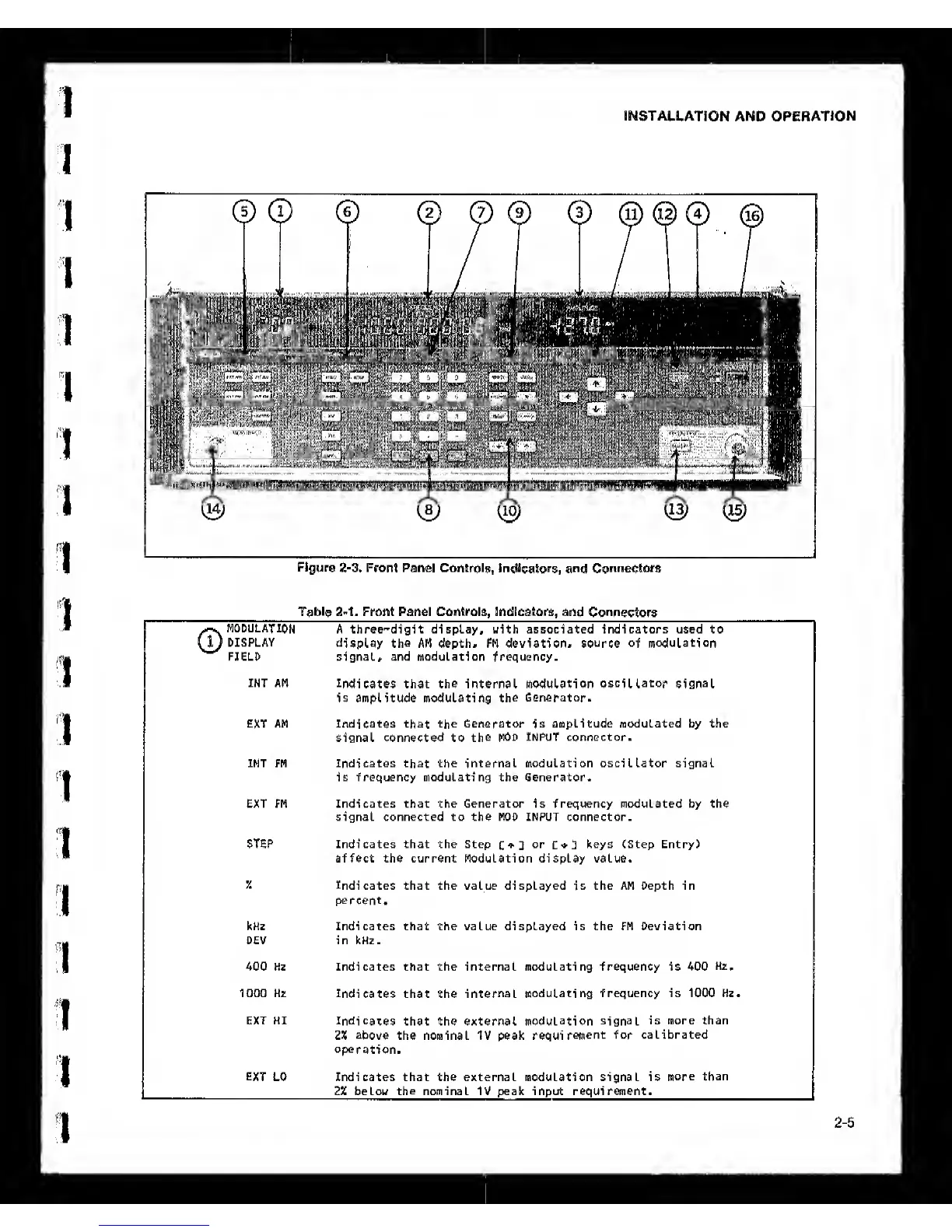
Table
2-1.
Front Panel Controls, Indicators, and
Connectors
1
1
1
1
1
MODULATION
A three-digit display, with associated indicators used to
DISPLAY
display the
AM depth# FM deviation#
source of modulation
FIELD signal# and modulation frequency.
INT AM
Indicates
that the internal modulation
oscillator signal
is amplitude modulating
the
Generator.
EXT AM Indicates
that
the Generator
is
amplitude modulated by the
signal connected to
the
MOD INPUT connector.
INT FM Indicates
that
the internal modulation oscillator signal
is frequency modulating the Generator.
EXT FM Indicates that the Generator is frequency modulated by the
signal connected to the MOD INPUT connector.
STEP Indicates that the Step
C 3
or
C
*
I]
keys (Step Entry)
affect the current Modulation display value.
y.
Indicates
that the value displayed
is
the AM Depth in
percent.
kHz Indicates that the value displayed is the FM Deviation
DEV in kHz.
400 Hz Indicates that the internal modulating frequency is 400
Hz.
1000 Hz
Indicates
that the
internal
modulating frequency is 1000 Hz.
EXT HI
Indicates
that the external
modulation signal
is more than
2%
above
the nominal IV peak
requirement
for calibrated
operation.
EXT
LO Indicates that the external modulation signal is
more than
2X belou
the
nominal IV peak input requirement.
2-5