INSTALLATION AND
OPERATION
2
-€
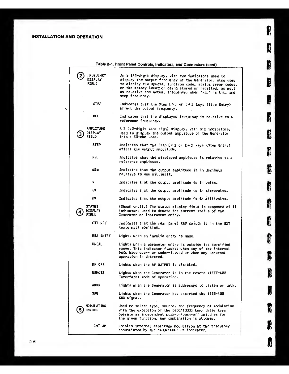
Table
2-1.
Front Pan»l
Controls, Indicatora,
and
Connectors (cont)
©
FREQUENCY
DISPLAY
FIELD
An 8
1/2-d1git
display, with two
indicators
used to
display the output
frequency
of the Generator.
Also
used
to display the
special function code,
status
error codes,
or the memory
Location
being stored
or recalled,
as well
as relative and
actual
frequency, when 'REL*
is lit, and
step frequency.
STEP
Indicates
that the Step or
keys (Step Entry)
affect the output
frequency.
REL
Indicates
that the displayed
frequency
is relative to a
reference
frequency.
©
AMPLITUDE
DISPLAY
FIELD
A
3 1/2“digit (and sign)
display, with six indicators,
used
to display the output
amplitude of the Generator
into a 50'Ohm Load.
STEP
Indicates
that the Step
or keys (Step Entry)
affect the output
amplitude.
REL
Indicates that the
displayed
amplitude is relative to a
reference
amplitude.
dBm
Indicates
that the
output
amplitude
is in
decibels
relative
to one milliwatt.
V Indicates
that the
output amplitude
is in
volts.
uV
Indicates
that the output amplitude
is
in
microvolts.
mV
Indicates that the
output
amplitude is in millivolts.
©
STATUS
DISPLAY
FIELD
(Shown unlit.) The status display field
Is
composed
of 11
indicators used to denote the current status
of
the
Generator
or Instrument entry.
EXT
REF
Indicates that the
rear panel REF switch is in the EXT
(external) position.
REJ ENTRY
Lights
when
an invalid entry is made.
UNCAL Lights
when
a parameter entry is outside its
specified
range.
This
indicator flashes when any of the internal
DACs have over- or under-flowed
or when
any
abnormal
operation is detected.
RF OFF
Lights
when the RF Output is disabled.
REMOTE Lights when the
Generator
is in the remote (IEEE-488
Interface) mode of operation.
ADDR
Lights
when the Generator is addressed to Listen or talk.
SRQ
Lights
when the Generator has asserted the IEEE-488
SRQ signal.
©
MODULATION
ON/OFF
Used to select type, source, and frequency
of
modulation.
With the exception of the C400/10003 key, these keys
Operate as independent push-on/push-off switches
for
the given function.
Any combination is
allowed.
INT AM Enables internal
amplitude modulation
at
the frequency
annunciated by the
'400/1000*
Hz indicator.