INSTALLATION
AND OPERATION
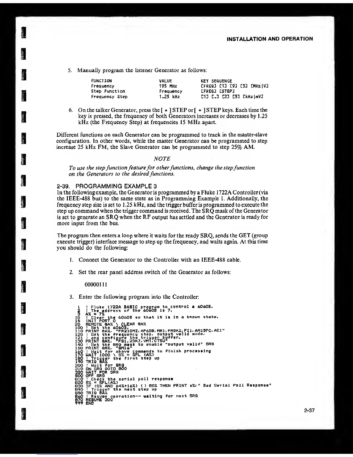
5. Manually program the listener Generator as follows:
FUNCTION
Frequency
Step Function
Frequency Step
VALUE KEY SEQUENCE
195 MHz CFREQJ
tU
192
C5D
CMHzlVJ
Frequency LFREQJ CSTEPJ
1,25
kHz
C13 Z.l C23 Z51
CkHzjmVn
6. On the talker Generator, press the
[ ]
STEP or[
*
]
STEP keys. Each time
the
key is pressed, the frequency of both Generators increases or decreases by 1.25
kHz (the Frequency Step) at frequencies
15
MHz apart.
Different
functions on
each
Generator
can be programmed to track
in the master-slave
configuration. In other words, while the master Generator can be programmed to step
increase 25 kHz FM, the Slave Generator can
be
programmed to step
25%
AM.
NOTE
To use
the
step
function
feature
for
otherfunctions, change the stepfunction
on the
Generators
to the desiredfunctions.
2-39.
PROGRAMMING EXAMPLES
In the following example, the Generator is programmed by a Fluke 1 722A Controller (via
the IEEE-488 bus) to the same state as in Programming Example 1. Additionally, the
frequency step size is set to 1 ,25 kHz, and the trigger buffer is programmed to execute
the
step up command when the trigger command is received. The
SRQ
mask of the Generator
is set to
generate an SRQ
when the RF
output has settled and the
Generator is
ready for
more input from the bus.
The program then enters a loop where
it waits
for the ready SRQ,
sends the GET
(group
execute trigger) interface message to step up the frequency, and waits again. At this
time
you should do the following:
1, Connect the Generator to the Controller with an IEEE-488 cable.
2. Set the rear panel address switch of the Generator as follows:
00000111
3.
Enter
the
following program into the
Controller:
1
‘
Fluke 1722A BASIC
program
to control a 6060B.
2 ! The address
of the 6060B is 7*
3 A% 7%
lO ! Clear the 6060B so
that it it In a
knomn
state,
15 INIT PORT 0
20 REMOTE «AX S
CLEAR
100 \ Set the 6060B.
110 PRINT €A%, "FRZIOMZ^
AP6I>BiMRl,FM5KZ»FU.AM15PC;AEl"
120 ! Set the frequency
step, output valid
mode.
122 ! and configure
the trigger buffer.
130 PRINT QAX. "FSl,
25K2. VMl, CTSU"
140 ! Set the SRQ mask to
enable "output
valid” SRQ
150 PRINT eA5t, ”Sm6''
160 ! Wait
for above commands
to
finish processing
170 WAIT 1000 \
SX
“
SPL <A7.>
IBO ! Trigger the
first
step up
190 TRIO SAX
300 ! Wait for SRQ
310
ON
SRQ
GOTO 800
320 WAIT FOR SRQ
800 OFF SRQ
810 ; Check the serial
poll response
820 SX
=
SPL (AX)
830 IF
(S% AND 64X+16X) < > 80%
THEN PRINT sX> ” Bad
Serial Poll Response"
840 ! Trigger the next step up
650 TRIO IaX
860 ! Resume
operation-- ualting for
next SRQ
870 RESUME 300
999 END
2-37