MAINTENANCE
TROUBLESHOOTING
AND
REPAIR
4D-8
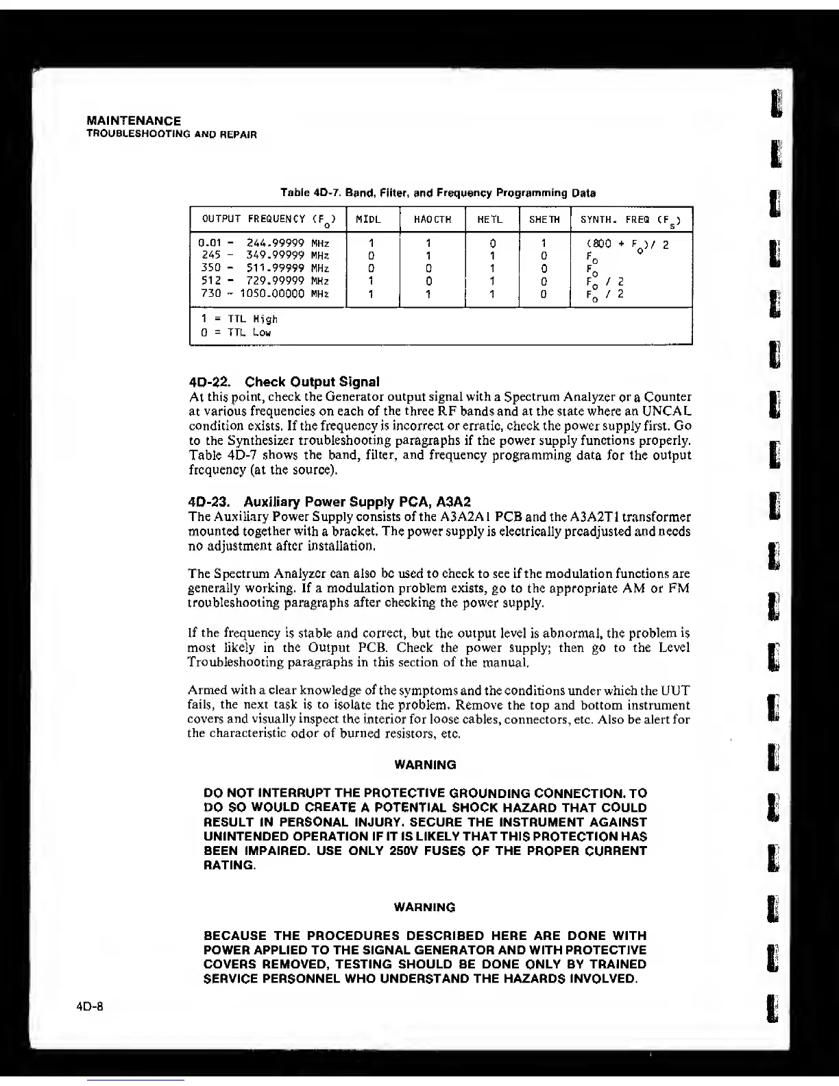
Table 4D-7.
Band,
Filter, and
Frequency
Programrning
Data
OUTPUT
FREQUENCY
(F )
o
MIDL HAO CTH HETL SHETM SYNTH. FREQ
CF^)
0.01
-
244.99999 MHz 1 1
0
1
(SOO
+
F
)/ 2
245
-
349.99999
MHs
0 1 1 0
350
-
511.99999
MHz 0
0
1
0
512
“
729.99999 MHz 1
0 1 0
730
-
1050.00000 MHz
1 1 1 0
1
=
TTL
High
0
=
TTL Low
4D-22.
Check Output Signal
At
this point, check the Generator output signal with a Spectrum Analyzer
or
a
Counter
at various
frequencies
on
each of the three RF
bands and
at the state
where
an
UNCAL
condition exists.
If
the frequency is incorrect or erratic, check the power supply first. Go
to
the Synthesizer troubleshooting paragraphs if
the
power supply functions properly.
Table
4D-7
shows the band, filter,
and
frequency
programming data for the output
frequency (at
the
source).
4D-23. Auxiliary
Power
Supply
PCA, A3A2
The Auxiliary Power Supply consists of the A3A2A 1
PCB
and
the
A3A2T1 transformer
mounted
together with
a bracket.
The
power supply is electrically preadjusted and needs
no adjustment after installation.
The Spectrum Analyzer can also be used to check to see if the modulation functions are
generally working. If a modulation problem exists,
go
to the
appropriate AM or FM
troubleshooting paragraphs after checking the
power supply.
If
the frequency
is stable
and correct, but the output level is abnormal, the problem
is
most likely in the Output PCB. Check the power supply; then go to the Level
Troubleshooting paragraphs in this section of the
manual.
Armed with a clear knowledge
of the
symptoms and the conditions under which the UUT
fails, the next task
is
to
isolate
the problem. Remove the top and bottom instrument
covers and
visually
inspect
the interior for loose cables, connectors, etc. Also be alert for
the characteristic
odor
of burned resistors, etc.
WARNING
DO
NOT INTERRUPT THE PROTECTIVE
GROUNDING CONNECTION. TO
DO SO
WOULD CREATE
A POTENTIAL SHOCK HAZARD THAT COULD
RESULT IN PERSONAL INJURY. SECURE THE INSTRUMENT AGAINST
UNINTENDED OPERATION IF IT IS LIKELY THAT THIS PROTECTION HAS
BEEN IMPAIRED. USE ONLY 250V FUSES
OF
THE PROPER CURRENT
RATING.
WARNING
BECAUSE THE PROCEDURES DESCRIBED HERE ARE DONE WITH
POWER APPLIED TO THE SIGNAL GENERATOR AND WITH PROTECTIVE
COVERS REMOVED, TESTING SHOULD BE DONE ONLY BY TRAINED
SERVICE PERSONNEL WHO UNDERSTAND THE HAZARDS INVOLVED.