MAINTENANCE
PERFORMANCE
TESTS
I
H
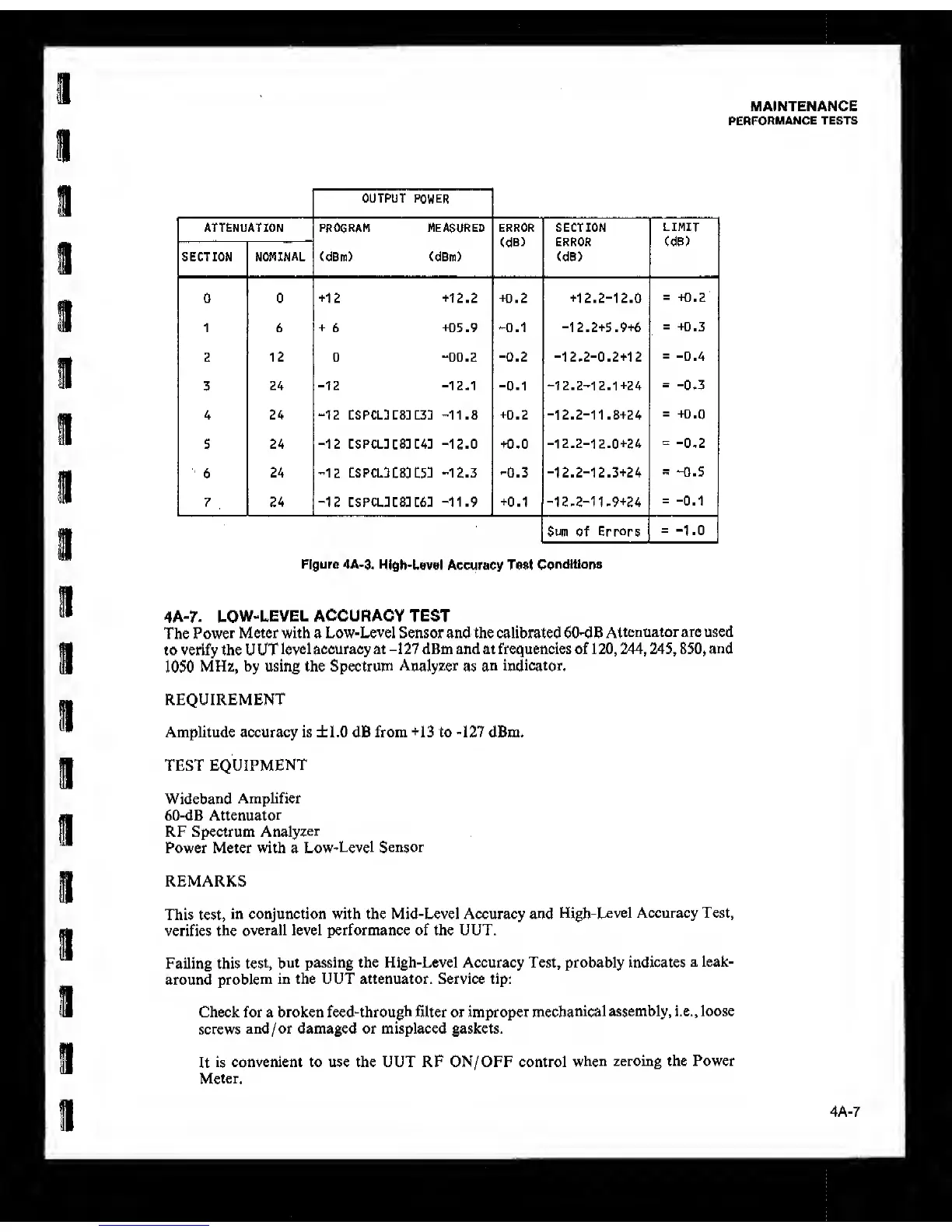
OUTPUT
POWER
ATTENUATION PROGRAM measured ERROR
(dB)
SECTION
LIMIT
(dB)
SECTION
NOMINAL
(dBm) (dBm) (dB)
0 0
+12 +12.2 +0.2 +12.2-12.0
=
-K).2
1 6
+
6
+05.9
-0.1 -12.2+5.9+6
=
+0.3
2 12 0 “0D.2
-0.2 -12.2-0.2+12
=
-0.4
3
24
-12 -12-1
-Q.1
“12.2-12.1+24
=
-0.3
4 24
“12
CSPCLKS: LZ2
-11.8
+0.2
-12.2-11.8+24
=
+0.0
5 24
-12
CSPCL]CS]C4]
-12.0
+0.0
-12.2-12.0+24
=
-0.2
6
24
"12
tSPCL3C83 C53
-12.3 -0.3 -12.2-12.3+24
-
“0.5
7
.
24
-12
cspcl:c8:c6:
-11.9
+0.1
-12-2-11-9+24
=
-0,1
Sum
of Errors
=
-1,0
Figure 4A-3.
High-Level Accuracy Test
Conditions
4A-7.
LOW-LEVEL ACCURACY TEST
The
Power
Meter with a Low-Level Sensor and the calibrated 60-dB
Attenuator are used
to verify the U UT
level accuracy at
-1
27 dBm and at frequencies of 1
20, 244, 245,
850,
and
1050
MHz, by using the Spectrum
Analyzer
as
an
indicator.
REQUIREMENT
Amplitude accuracy is ±1.0 dB from
+13
to
-127
dBm.
TEST
EQUIPMENT
Wideband
Amplifier
60-dB
Attenuator
RF Spectrum
Analyzer
Power Meter with a
Low-Level
Sensor
REMARKS
This test,
in conjunction with the Mid-Level Accuracy and
High-Level Accuracy Test,
verifies the
overall level performance of the UUT.
Failing this
test,
but passing the High-Level Accuracy Test, probably indicates
a leak-
around
problem
in the UUT attenuator. Service tip:
Check for a broken
feed-through
filter or improper
mechanical
assembly, i.e.
,
loose
screws
and/or damaged or misplaced gaskets.
It
is
convenient to use the UUT RF ON/OFF control
when
zeroing the Power
Meter.
4A-7