MAINTENANCE
PERFORMANCE TESTS
This test verifies the high-level accuracy of the Generator and also verifies that the
amplitude
correction factors for the
individual
Attenuator sections are correct. This
test,
in conjunction with the mid-level accuracy and low-level accuracy tests, verifies the
overall level performance of the UUT.
PROCEDURE
a. Calibrate and zero the Power Meter.
b. Program the
UUT
to [RCL]
[9][8].
c.
Connect the
Power Sensor to the UUT RF OUTPUT.
d. Program the UUT frequency to 0.4 MHz.
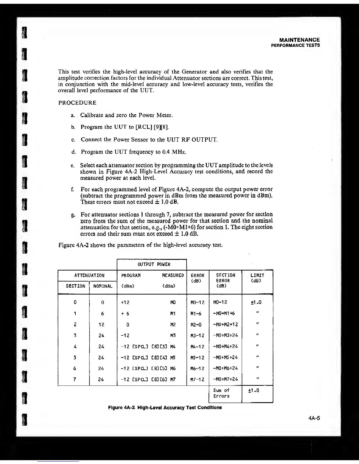
e. Select each attenuator section by programming the UUT amplitude to the
levels
shown in Figure 4A-2
High-Level
Accuracy
test conditions, and record the
measured power at each level.
f. For
each programmed level of Figure 4A-2, compute the output
power
error
(subtract
the
programmed power in dBm
from the measured power in dBm).
These errors
must
not exceed ±
1.0 dB.
g.
For attenuator sections 1 through
7,
subtract the
measured
power for section
zero from the sum of the measured
power
for that section and the nominal
attenuation for that section, e.g., (-M0+M1+6) for section 1. The eight section
errors and their sum must not exceed ± 1.0 dB.
Figure 4A-2 shows the
parameters of the high-level accuracy test.
OUTPUT POWER
ATTENUATIOM program MEASURED ERROR
(d8)
SECTION
ERROR
<dB>
LIMIT
(dB)
SECTION NOMINAL
CdBm)
(dBm)
0 0
+12
MO MO-12 MO-12 ±1 .0
1
6
+
6
Ml
MI-6
-M0+M1+6
2 12
0
M2
M2-0
-MO+M2+12
M
3 24
-12
M3
M3-12
-M0+M3+24
II
4 24
-12
CSPCL1 L&2ZZ2 M4 M4-12
-M0+M4+24
H
5 24
-12
CSPCL3 ES:C4: M5 M5-12
-MD+M5+24
II
6 24
-12
cspcl: tSlL52 M6 M6-12
-M0+M6+24
f|
7 24
-12
CSPCL] :S3:6] M7 M7-12
-MQ+M7+24
"
Sum of
Errors
±1-0
Figure 4A-2.
High-Level
Accuracy
Test
Conditions
4A-5